Blade Axis Systems
The blades in Bladed are defined as a series of 2D sections, distributed along the blade's span. The structural model is represented by a series of nodes connected by straight beam elements. The aerodynamic model is represented by lift, drag and moment polars defined for each section.
This section summarises the coordinate systems used to define the structural and aerodynamic properties.
The Blade Root Coordinate System
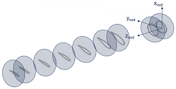
The blade root coordinate system is the orthogonal axes system in which the blade sections are positioned.
The origin for the blade root system is the attachment point to the rest of the turbine, it is a calculated set of properties that cannot be changed directly at the blade component definition. Most often, the blade will be attached the bearing of the pitch system in which case the root coordinate system will be defined by the BladeMounting property options. The blade root coordinate system rotates with the rotor's axis of rotation, as well as about the pitch axis.
The axes directions are summarised as follows:
| Axis | Alignment |
|---|---|
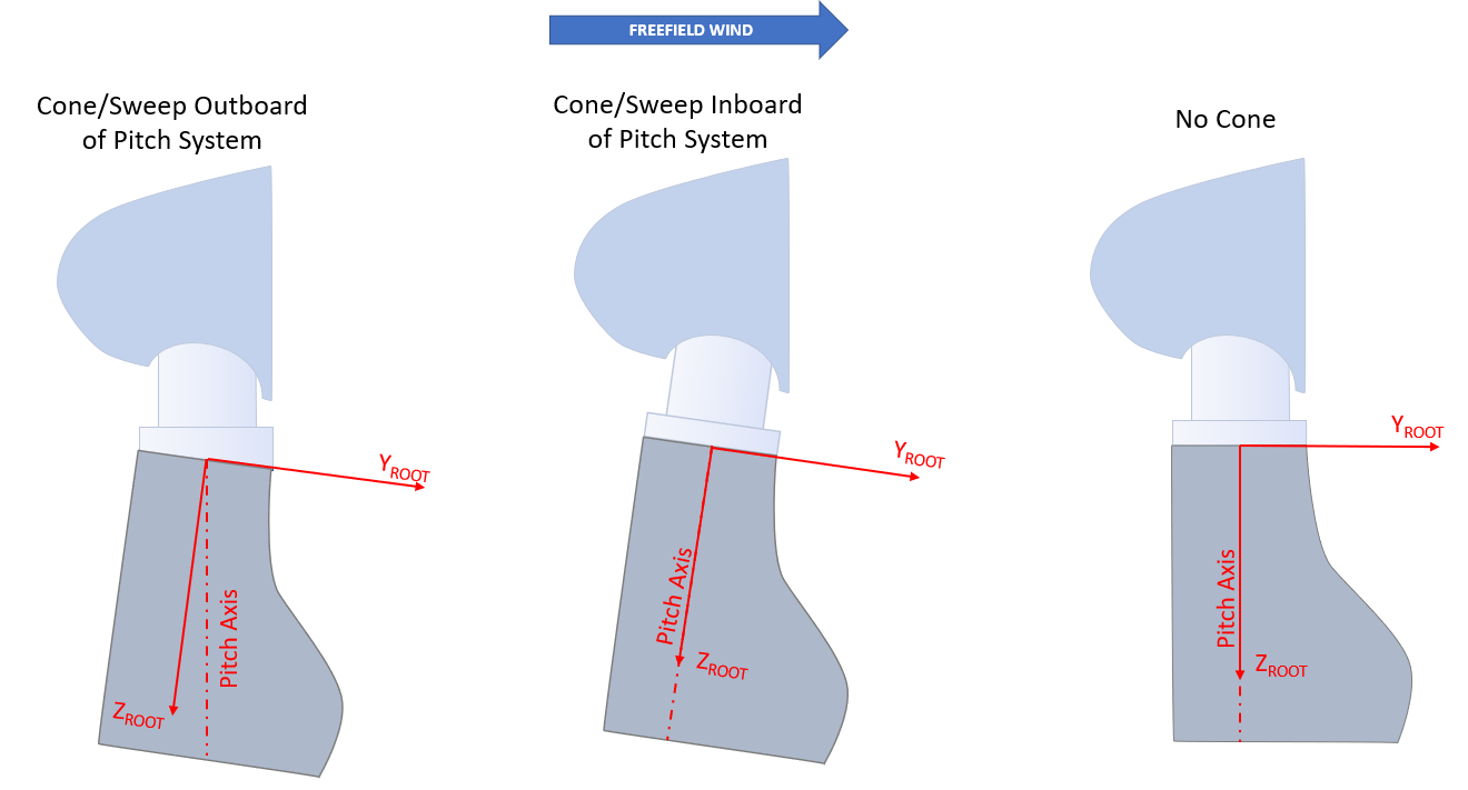
| \(\underline{X}_{root}\) | When the rotor cone angle, blade mounting cone angle, and the blade pitch angle are zero, the blade \(\underline{X}_{root}\) axis is parallel to the rotor rotational axis. |
| \(\underline{Y}_{root}\) | The \(\underline{Y}_{root}\) axis follows from the right-hand rule convention. |
| \(\underline{Z}_{root}\) | The \(\underline{Z}_{root}\) axis points along the blade towards the blade tip. This is equal to the pitch axis of the blade if there is no sweep or cone outboard of the pitch bearing. |
It is important to note that both blade mounting cone and sweep can be applied outboard of the pitch bearing, meaning that the blade \(\underline{Z}_{root}\) axis is not necessarily the same as the pitch axis.
Blade Sections
The properties of the turbine blade are specified at a series of 2D sections along the blade.
The number, position, and orientation of these planes can be specified by the user.
The structural and aerodynamic properties must be specified on each of these planes, each in their own coordinate systems (see Blade Section Definition). Bladed assumes that the structural properties vary linearly from one section to the next.
The Sections' Reference Systems
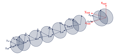
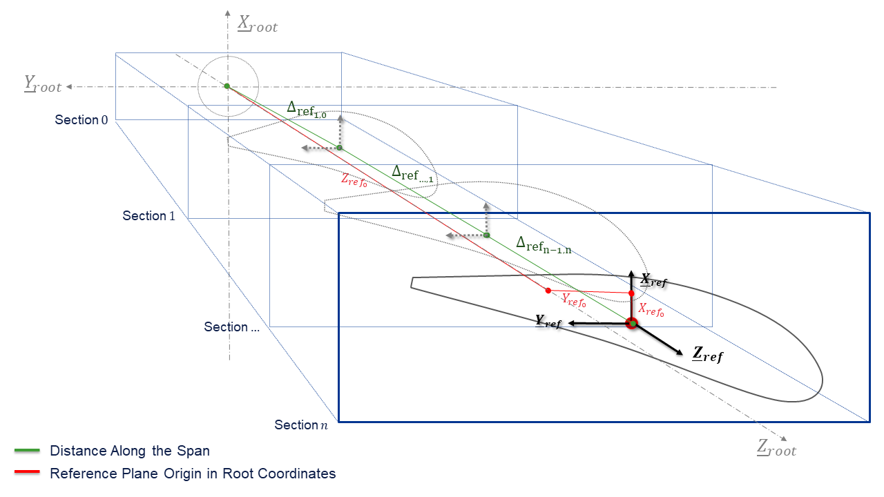
Each of the section planes are defined in the blade root coordinate system. Each section plane has an origin point \([X,Y,Z]_{\mathrm{ref}_0}\)) (Origin), a \(\underline{Z}_{\mathrm{ref}}\) axis (ZAxis defining the section plane's normal), and a \(\underline{Y}_{\mathrm{ref}}\) axis (YAxis), which together define an orthogonal coordinate system referred to as the section's reference coordinate system (ReferenceCoordinateSystem).
All of the properties for the section (such as stiffnesses, masses, etc.) are then defined in specific coordinate systems which are defined in relation to this reference system (see Blade Section Definition).
The origin of each reference system defines a reference location with respect to which other axis origins are defined. This can be assumed to represent any chosen location in the blade section, such as on the leading edge of the section, at the half-chord, or at the neutral axis. Because all of the section properties are defined in relation to the reference system, if the reference system is moved or rotated, all of the section property coordinate systems will move and rotate by the same amount.
Within the SectionDefinitions, the users can set the Origin, the ZAxis and the YAxis of the ReferenceCoordinateSystem. The Origin point of the reference section coordinate system can also be defined by the distance of the section to the root along the blade span line (DistanceAlongSpan). This distance is calculated as the distance between the root and consecutive aerofoil reference axis origin points (see Figure-5), whereas:
Only the Origin's Z (\(Z_{ref_0}\)) coordinate or as an alternative theDistanceAlongSpan are an absolute requirement to define the section plane. All section reference planes in the same blade should be defined using the same options, whereas the code does not prevent the user from mixing both options, the outcomes might not be what the user expects. In the same way the sections will always be represented in the blade geometry as monotonically increasing in distance from the root.
| Property | Units | Default Behaviour |
|---|---|---|
Origin.X |
meters | Defaults to \(X_{\mathrm{ref}_0}=0.0\) |
Origin.Y |
meters | Defaults to \(Y_{\mathrm{ref}_0}=0.0\) |
Origin.Z or DistanceAlongSpan |
meters | Required user input \(Z_{\mathrm{ref}_0}\) or \(\Delta_{\mathrm{ref}}\) |
ZAxis |
[ , , ] | Defaults to the average direction from the last section's Origin to the next section's |
YAxis1 |
[ , , ] | Defaults to the rotation of the blade Y-axis axis onto the section plane |
The default orientation of the reference section plane's axis depend of the values set to the Origin point of that section and the location and orientation of the previous (closest on the root direction) defined section.
-
The reference system's \(\underline{X}_{ref}\) axis is not an input, but is calculated by a cross product of the \(\underline{Y}_{ref}\) and \(\underline{Z}_{ref}\) vectors to produce a vector normal to both. The \(\underline{Z}_{ref}\) and \(\underline{X}_{ref}\) are then crossed with each other once more to produce a rectified \(\underline{Y}_{ref}\) such that the axis set obeys the right-hand convention.↩