Aerodynamic Outputs
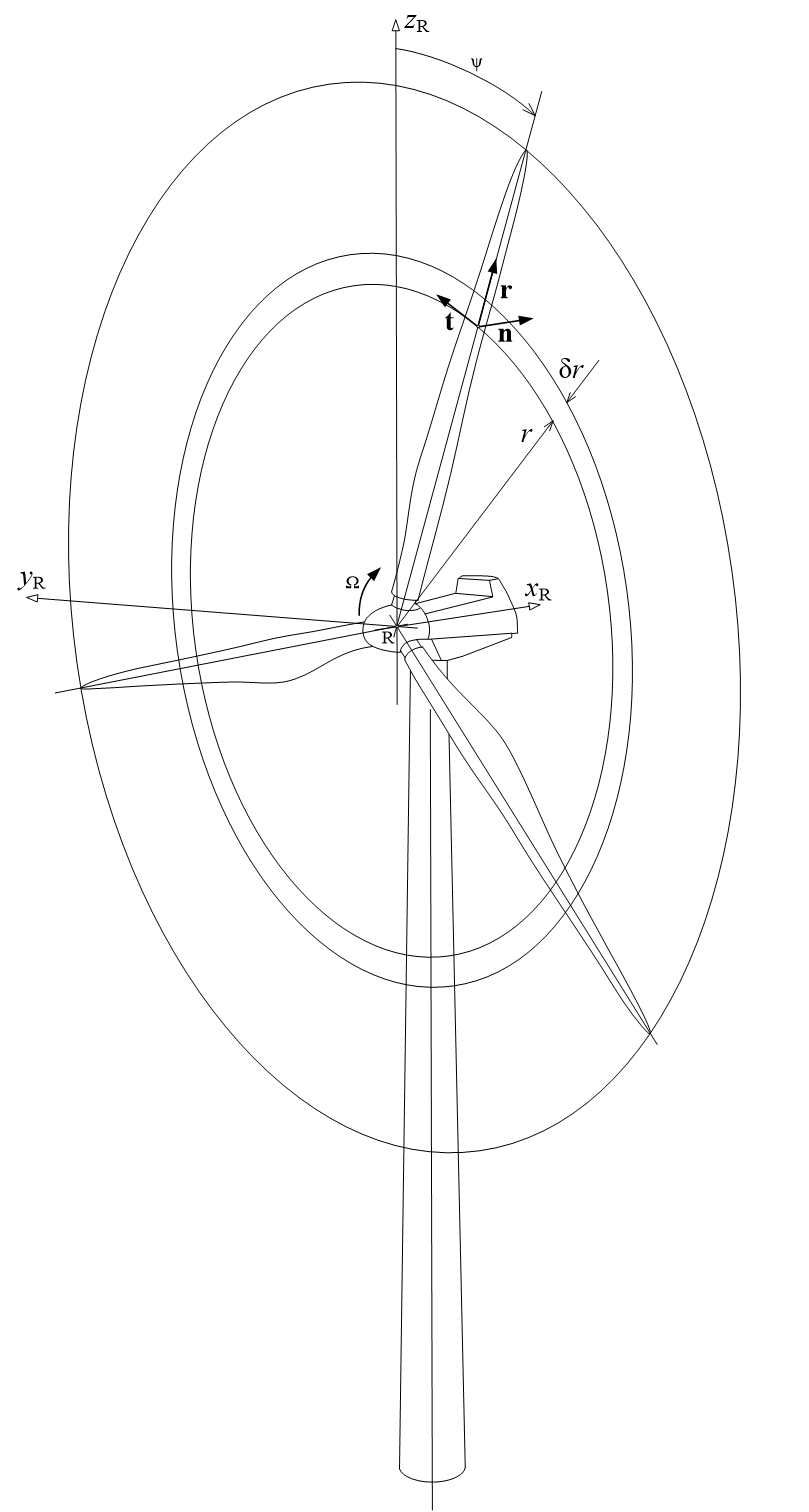
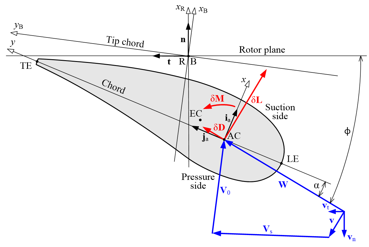
The outputs of the aerodynamic performance and loading calculations in Bladed are explained. To understand the outputs, the definitions of the rotor axial/tangential direction are defined in the figures below. Note that “axial” indicates in direction of vector \(n\) normal to the rotor plane and tangential indicates in the direction of tangent vector \(t\). Further note that the radial vector \(r\) assumes an un-coned rotor. These do not change with respect to blade pitch angle.
Table 1 lists all the aerodynamic outputs with descriptions and the output coordinate system used. The relevant coordinate systems include the blade coordinate system shown in Figure 1 and the aerofoil coordinate system shown in Figure 2.


| Variable name | Explanation | Coordinate system |
|---|---|---|
| Axial induction factor | Velocity induced by rotor in axial direction normalised by the free stream flow speed | Blade Figure 1 | |
| Tangential induction factor | Velocity induced by rotor in tangential direction normalised by rotational speed times local radius | Blade Figure 1 |
| Axial induced velocity | Velocity induced by rotor in axial (normal) direction | Blade Figure 1 |
| Tangential induced velocity | Velocity induced by rotor in tangential direction | Blade Figure 1 |
| Tip/hub loss factor | Magnitude of tip/hub loss factor | Not applicable |
| Inflow angle | Angle between effective flow speed velocity vector and tangential direction of rotor plane (\(\phi\) in the figure) | Aerofoil Figure 2 |
| Angle of attack | Angle between effective flow speed vector and local chord line (\(\alpha\) in the figure) expressed at the quarter chord point | Aerofoil Figure 2 |
| Angle of attack rate of change | Time derivative of angle of attack expressed at the quarter chord point | Aerofoil Figure 2 |
| Reynolds number | Reynolds number computed at the blade section | Not applicable |
| Lift coefficient | Dynamic lift coefficient including the dynamic stall effects (if being activated) – defined at the quarter chord point | Not applicable |
| Drag coefficient | Dynamic drag coefficient including the dynamic stall effects (if being activated) – defined at the quarter chord point | Not applicable |
| Pitching moment coefficient 1 | Dynamic pitching moment coefficient including the dynamic stall effects (if being activated) – defined at the quarter chord point | Not applicable |
| Incident axial wind speed | Axial component of the incident wind velocity vector | Blade Figure 1 |
| Incident tangential wind speed | Tangential component of the incident wind velocity vector | Blade Figure 1 |
| Relative normal to chord wind speed | Normal to chord component perpendicular to the chord line of the relative wind velocity vector including effect of induction | Aerofoil Figure 2 |
| Relative chordwise wind speed | Chordwise component of the relative wind velocity vector including effect of induction | Aerofoil Figure 2 |
| Relative wind speed | Relative wind speed including effect of induction | Aerofoil Figure 2 |
| Axial aerodynamic force | Axial component of aerodynamic load per unit length | Blade Figure 1 |
| Tangential aerodynamic force | Tangential component of aerodynamic load per unit length | Blade Figure 1 |
| Aerodynamic twisting moment | Aerodynamic moment about the elastic axis per unit length. Orientation of moment axis is in direction of unit vector “r“ | Blade Figure 1 |
| Chordwise Aerodynamic force | Aerodynamic force in direction of the chord line | Aerofoil Figure 2 |
| Normal to chord aerodynamic force | Aerodynamic force perpendicular to the chord line | Aerofoil Figure 2 |
-
Bladed will convert the pitching moment coefficient \(C_m\) such that it is defined at the quarter chord point regardless of how it was defined in the input. The output of pitching coefficient will not correspond to the original aerofoil chordwise origin for forces and moments defined by the user in the aerodynamic polar input panel \(C_m^{XA}\). Bladed applies the following transformation to convert the input \(C_m^{XA}\) to \(C_m\) used for computation:
\[ \begin{equation} C_m = C_m^{XA} + C_l (0.25 – Xa) \cos \alpha + C_d (0.25 – Xa) \sin \alpha \end{equation} \]with \(C_l\), \(C_d\), \(XA\) and \(\alpha\) specifying the lift coefficient, drag coefficient, the aerofoil chordwise origin for forces and moments and the angle of attack, respectively.↩