Blade Outputs
Bladed provides both load and kinematic outputs for the blades in various coordinate systems. The outputs all use either distance along the blade or the time as the x-axis.
Load Outputs
The loads can be specified independently about the following axes: Principal Axes, Root Axes and Aerodynamic Axes. Within each group, the loads are labelled: \(M_x, M_y, M_{xy}, M_z, F_x, F_y, F_{xy}, F_z\).
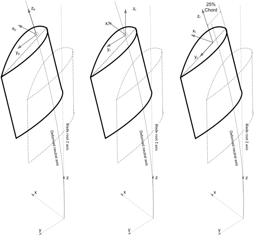
Figure 1 illustrates the available coordinate systems.

Principal Axes
The Principal Axes coincide with the NeutralAxisCoordinateSystem, which changes as the blade deflects. The orientation of the principal axes uses the average orientation of the two blade elements at the node where the elements join of the underlying element frames. The positive z-axis follows the local deflected neutral axis at each blade section towards the blade tip. The positive y-axis is defined by the principal axis orientation (average of the deflected element frames). The positive x-axis is orthogonal to the y and z and follows the right-hand rule, as shown in Figure 1.
Root Axes
The Root Axes coincide with the NeutralAxisCoordinateSystem, but it is oriented according to the blade root coordinate system. Consequently, it remains fixed during twist or blade deflection, but it does rotate around the z-axis as the pitch changes. Additionally, the origin of the NeutralAxisCoordinateSystem shifts with blade deflection, resulting in a corresponding change in the origin of the Root axes load output.
Aerodynamic Axes
The Aerodynamic Axes originate at the QuarterChordCoordinateSystem. However, a slight approximation is applied, as it transforms the principal axes loads and applies a rotation with an angle corresponding to the difference between the NeutralAxisCoordinateSystem and QuarterChordCoordinateSystem. This approximation introduces a small error since the principal axes represent an average of the underlying element frame and are not equal to the NeutralAxisCoordinateSystem.
The transformation is done to account for the additional Mx and My bending moments that are generated at the Aerodynamic centre by the element axial force Fz in the Principal Axes system, due to the offset in the aerofoil plane between these two coordinate centres. This effectively estimates the load that would have occurred if the load was carried through an axis at the Aerodynamic Axis centre. There is some approximation in this method as the Aerodynamic are not the true load path. Any changes to the blade dynamics (e.g. deflections or loads) that might result from such a change in load path are not accounted for.
The x-axis is perpendicular to the local chord line and the positive y-axis is aligned along the local chord line from the leading edge to the trailing edge. The z-axis is parallel to the deflected z-axis of the principal axis at each blade section. In Figure 1 the \(y_r\)-component points towards the trailing edge of the aerofoil. However, for anticlockwise configurations the \(y_r\)-component points towards the leading edge as the aerofoil is rotated. Thus the orientation of the aerodynamic axes does not change between clockwise and anticlockwise rotors.
Kinematics Outputs
Bladed provides outputs for the blade deflections and the absolute blade positions.
Deflections
The Deflection output provides the blade deflections defined in two coordinate systems: in the blade root coordinate system and in the coned and swept rotor plane (before blade set angle and pitch are applied). The deflections are based on the NeutralAxisCoordinateSystem positions along the blade.
Absolute Motion
The absolute positions of the blade are provided at the NeutralAxisCoordinateSystem positions along the blade. These positions are given in the global frame, as described in the documentation. The resulting output group is labelled Absolute motion.