Blade Section Properties
Property Coordinate Systems
There are three categories of properties applicable to each blade section: StructuralProperties, MassProperties, and AerodynamicProperties. Each property is defined relative to an origin and often includes orientation information, such as bending stiffnesses about X and Y axes. Consequently, this leads to the establishment of four property coordinate systems, each associated with one of the three property groups outlined in Table 1.
| Property Group | Coordinate System Name | Origin | Orientation |
|---|---|---|---|
StructuralProperties |
NeutralAxisCoordinateSystem |
The neutral axis of the section | The principal bending axes |
StructuralProperties |
ShearAxis |
The shear centre of the section | There is no orientation for the ShearAxis |
MassProperties |
MassCoordinateSystem |
The centre of gravity of the section | The mass principal axes |
AerodynamicProperties |
QuarterChordCoordinateSystem |
The quarter-chord position, located 1/4 of the way along the chord-line | The Y-axis will point from the leading edge to the trailing edge |
Transformation From Reference System to Property System
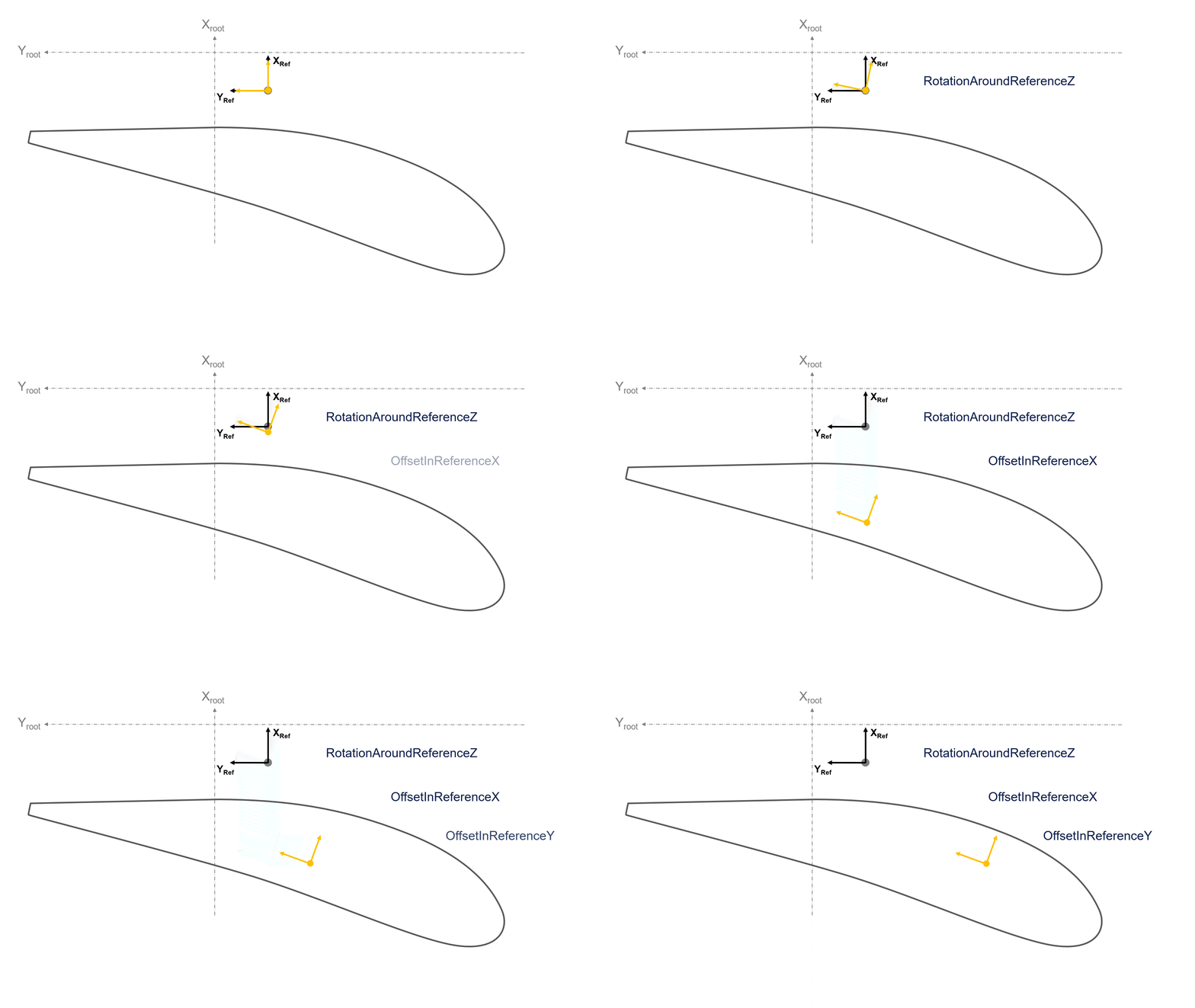
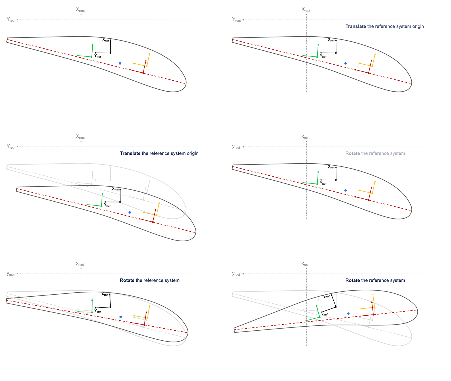
The XY plane of the reference coordinate system defines the plane in which all of the section's properties are defined. The other coordinate systems and loci are defined in the reference XY plane, but with an optional rotation about reference \(Z_{ref}\) axis and a subsequent (also optional) translation in the reference \(X_{ref}\) or \(Y_{ref}\) systems. Both transformations occur in the reference system, such that the rotation and subsequent translation are decoupled (i.e. you can change the rotation without affecting the position, and vice-versa). This is illustrated in the animation below.

Each of the property coordinate systems have the following properties:
| Property | units | Description | Default |
|---|---|---|---|
RotationAboutReferenceZ |
radians | The rotation - following the right-hand convention - of the coordinate system about the reference \(Z_{ref}\) axis before translation | 0.0 |
OffsetInReferenceX |
meters | The X position of the property axis origin in the reference coordinate system | 0.0 |
OffsetInReferenceY |
meters | The Y position of the property axis origin in the reference coordinate system | 0.0 |
If any single property is omitted, it will default to 0.0. If the entire section is omitted for one of the coordinate systems, then all of these values will remain at their default value of 0.0 - meaning that the coordinate system will be coincident with the reference coordinate system.
All four property systems are transformed from the reference system in a similar manner.
As all of the property coordinate systems are defined in terms of the reference coordinate system, if the reference coordinate system is moved or rotated (by modifying its Origin, ZAxis or YAxis), then all of the property coordinate systems will move and rotate with it.

Overview of Coordinate System Names and Property Groups
| Coordinate System Name | Associated Property Group | Associated Properties in Group |
|---|---|---|
NeutralAxisCoordinateSystem |
StructuralProperties |
BendingStiffnessAboutX |
BendingStiffnessAboutY |
||
AxialStiffness |
||
ShearStiffnesses |
||
CouplingTerms |
||
ShearAxis |
StructuralProperties |
TorsionalStiffness |
QuarterChordCoordinateSystem |
AerodynamicProperties |
Chord |
ThicknessToChordRatio |
||
AerodynamicSection |
||
MassCoordinateSystem |
MassProperties |
MassPerUnitLength |
MomentOfInertia |
||
RadiusOfGyration |
Any of these properties or property groups can be omitted with the exception of the AerodynamicProperties and its three properties, which are required to define the section's aerodynamic behaviour.
Where a stiffness is omitted, Bladed will assume that it is rigid in that degree of freedom. If the entire StructuralProperties group is missing, then it will model it as rigid.
Warning
In the current implementation, any given stiffness must be provided for the entire blade or none of it. This means that you can't have a rigid element on an otherwise flexible blade, or vice versa.
Note
To set a given degree of freedom to be rigid, you can search for the respective keyword and replace it with an underscored version: for example, to make the blade rigid in extension, replace all "AxialStiffness" with _AxialStiffness.

