Finite Element Model and Modal Reduction
The structural formulation in Bladed is based on the finite element method (FEM), which is a computational technique used for solving structural dynamics problems. It discretises a structural system into smaller elements, each with specific physical properties (such as density, Young’s modulus, shear modulus and so on). These elements are interconnected at discrete points called nodes, forming the overall structural model which is referred to as the flexible body. An illustration of how the blade is discretised into a flexible body can be seen in Figure 1 using a fixed boundary condition. For further details refer to the introduction to flexible components section.
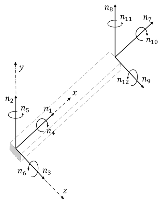
With the basic finite element method the flexible body is described by six degrees of freedom at each node, which means that the complete flexible body will have \(6(n-1)\) degrees of freedom taking into account that the displacement at the proximal node is assumed to vanish (fixed boundary condition). Figure 2 shows the degrees of freedom at each node of a flexible body consisting of a single beam in three dimensions.

The flexible body of the blade is based on the section properties of the NeutralAxisCoordinateSystem and StructuralProperties. This will create \(6(Sections-1)\) degrees of freedom, which can significantly increase the computational effort due to the large number of freedoms involved for long and complex blades. Hence a method to effectively reduce the number of freedoms while still keeping the fidelity and accuracy is preferable and Bladed utilises the method of Modal Reduction.
The user can enable the complete finite element model by using the FiniteElementBladeModelling option for the BladeModellingType property, however, this is not recommended from a calculation speed perspective.
Modal Reduction
An efficient way of increasing the calculation speed is to reduce the number of degrees of freedom that describes the present deformation state of the system by eliminating high frequency modes that do not contribute significantly to the dynamics of the body. This is achieved by expressing the current deformation state in terms of a number of so-called mode shape functions that describe a pre-calculated pattern of the nodal coordinates. This functionality can be switched on by using the ModalBladeModelling option for the BladeModellingType property. The number of included mode shapes is determined by the input NumberOfModesPerBladePart, where the "Part" refers to the multi-part blade definition.
Mode Shapes
The flexible body of the blades can be represented as a finite element model with fixed boundary condition at one end, as depicted in Figure 1. By performing an eigenvalue analysis on this structure, we can compute a set of mode shapes corresponding to the number of degrees of freedom in the model. The eigenvectors of the analysis correspond to the mode shapes which describe the different vibrational patterns. The resulting eigenvalues correspond to associated frequencies.
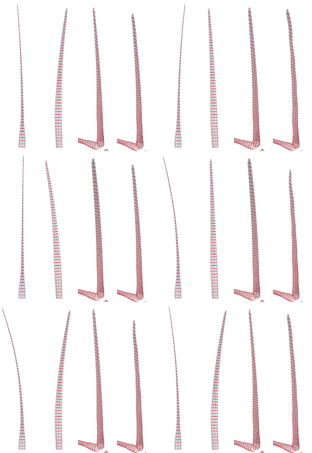
The types of mode shapes of a blade are (see Figure 4 for visualisation):
Flapwise: Refers to the bending of the blade about the Y-axis. Imagine the blade flexing up and down like a flap. This will often be the most flexible degree of freedom with the lowest frequency.Edgewise: Involves bending of the blade about the X-axis. Picture the blade bending from side to side. Often stiffer than the flapwise direction.Torsional: Occurs when the blade twists around its longitudinal axis (Z-axis). Think of the blade twisting like a corkscrew, changing the angle of attack.Axial: It refers to changes along the blade’s axial direction (Z-axis). Axial deformation is less commonly discussed in the context of wind turbine blades as it is often a very stiff degree of freedom, having a high frequency and low impact to the overall dynamics.
In the single-part blade model, only normal modes are used. When the multi-part blade model is selected, the inner parts use both normal and attachment modes, while the outermost part uses only normal modes. For further details, please see the normal and attachment modes and blade mode shapes theory sections.
An illustration of the 1st and 2nd edgewise mode shapes can be seen in Figure 3 and different mode shape types can be seen in Figure 4.


