Finite Element Model and Modal Reduction
The structural formulation in Bladed is based on the finite element method (FEM), which is a computational technique used for solving structural dynamics problems. It discretises a structural system into smaller elements, each with specific physical properties (such as thickness, density, Young’s modulus, shear modulus and so on). These elements are interconnected at discrete points called mesh nodes, forming the overall structural model which is referred to as the flexible body.
An illustration of how the tower is discretised into a series of beams adjoined by tower mesh nodes can be seen in Figure 1 using a fixed boundary condition. The tower nodes are defined at the adjoining location between tower Cans. In addition, there is a node at the tower base and the tower top. Nodes are important for the reporting of outputs such as tower kinematics and loads.
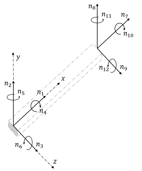
With the basic finite element method the flexible body is described by six coordinates at each node, which means that the complete flexible body will have \(6(n-1)\) degrees of freedom taking into account that the displacement at the proximal node is assumed to vanish (fixed boundary condition). Figure 2 shows the degrees of freedom at each node of a flexible body consisting of a single beam in three dimensions.

Each tower Can defines a single beam and adjoins to other Cans via a node at the base and top sections of each Can. This does not apply to the Cans at the tower base and tower top as these will only adjoin to a single Can. The section properties of the Cans define the stiffness and mass data at the nodes. In total this will create \(5(Nodes-1)\) degrees of freedom for the entire tower.
Note
The axial degree of freedom is disabled by default for the tower.
Tall and detailed tower representations can lead to a large number of nodes. This significantly increases the computational effort due to the large number of degrees of freedom that need to be solved. Hence a method to effectively reduce the number of degrees of freedom while maintaining accuracy is preferable. Bladed thereby utilises the method of Modal Reduction to simulate the tower flexible body.
Modal Reduction
An efficient way of increasing the calculation speed is to reduce the number of degrees of freedom that describes the present deformation state of the system by eliminating high frequency modes that do not contribute significantly to the dynamics of the body. This is achieved by expressing the current deformation state in terms of a number of so-called mode shape functions that describe a pre-calculated pattern of the nodal coordinates. This functionality can be switched on by using the ModalStructuralModelling option for the StructuralModellingType property.
Mode Shapes
The flexible body of the tower may be represented as a finite element model with fixed boundary condition at the tower base, as depicted in Figure 1. By performing an eigenvalue analysis on the finite element representation of the structure, we may compute a set of uncoupled mode shapes (or simply mode shapes) corresponding to the number of degrees of freedom in the model. The eigenvectors of the analysis correspond to the mode shapes which describe the different vibrational patterns. The eigenvalues of each mode shape represent the frequency of that mode.
The tower mode shapes define the deflection of the mesh nodes relative to the body-fixed frame. A summary of common names of tower mode shapes and their meanings are listed below.
Fore-aft: Refers to bending of the tower causing tower mesh nodes to move backwards and forwards parallel to the body-fixed \(x_b\) axis.Side-side: Refers to bending of the tower causing tower mesh nodes to move side to side parallel to the body-fixed \(y_b\) axis.Torsional: Tower twist about the body-fixed \(z_b\) axis.
The number of tower uncoupled mode shapes that will be included in the calculation is equal to the number of modes that have been assigned a damping ratio. The damping ratio is assigned to the mode shapes in order of ascending frequency. The number of mode shapes that are included to simulate tower flexibility will impact how the tower deflects. For instance, by only including a single fore-aft mode shape will constrain the motion of the mesh nodes to translate backwards and forwards parallel to the \(x_b\) axis.
Bladed utilises a combination of attachment modes and normal modes in the modal reduction routine. For further details, please see the normal and attachment modes and tower mode shapes theory sections.
An illustration of the 1st tower fore-aft normal and attachment mode shapes can be seen in Figure 3. The deflection of each tower node in the body-fixed \(x_b\) axis is provided for both mode shapes. The deflections are normalised by the largest displacement.
Mesh Node Frame
When the tower is not deflected, the reference frame of each mesh node will have its origin at the mesh node and the axes \((x_m, y_m, z_m)\) will match the body-fixed axes. During a simulation, the modal deflection of the tower will displace and rotate the tower mesh node frames as shown in Figure 4. The distal frame will also be displaced and rotated by modal deflection as well.


