Rotation Conventions
Overview
This article aims to explain the rotation conventions, axis-angle and Euler angle, that are used in Bladed. The core calculation of multibody dynamics in Bladed uses axis-angle convention and consequently, the results are calculated in axis-angle convention. However, Bladed output data are detailed in their components (x, y, z) under different output groups. In some specific cases, Euler angle convention is utilized in Bladed to report data as it is needed. In those cases,a transformation from axis-angle convention to Euler angle convention is required. The following subsections explain how these transformations are implemented in Bladed.
Axis-angle frame vs Euler angle frame
The axis-angle convention is a representation of any rotation or series of rotations in three-dimensional space as equivalent to a rotation of the geometry around a single fixed axis. In this convention, the rotation is
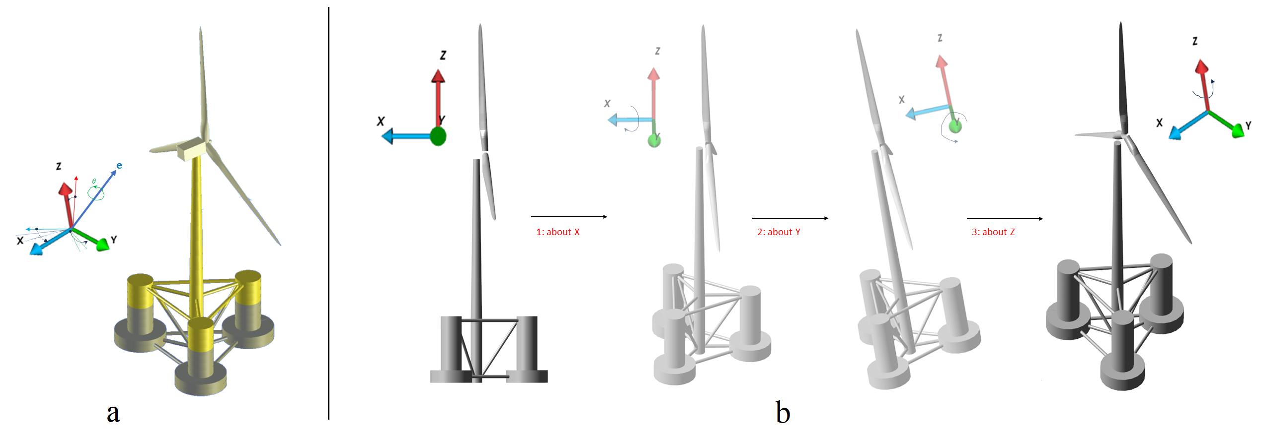
expressed by a unit vector \(e\) indicating the axis of rotation and an angle of rotation \(\theta\) describing the magnitude and direction (e.g., clockwise) of the rotation about that axis (see Figure 1_a).
On the contrary, the Euler angle convention involves three successive rotational angles, known as Euler angles, to describe the orientation of a rigid body (see Figure 1_b).
The final orientation of the coordinate system can be defined using any sequence of rotations, as long as consecutive rotations are not around the same axis. The Bryant angle, a specific form of the Euler angle convention,
ensures that the three successive rotations are not repeated, such as in the order of X-Y-Z or Z-Y-X. This rotation convention is commonly employed in engineering applications.
It is worth noting that Euler angles are defined by intrinsic rotations or extrinsic rotations. The elemental rotations can either occur about the axes of the fixed coordinate system (extrinsic rotations)
or about the axes of a rotating coordinate system, which is initially aligned with the fixed one and modifies its orientation after each elemental rotation (intrinsic rotations).
Transformation matrix using axis-angle and Transformation matrix using Euler angle describe the calculation of rotation matrix
in axis-angle convention and Euler angle convention, respectively.

The axis-angle convention is employed to specify the orientation of initial mooring position in Bladed UI. Bladed calculates the kinematics results in the axis-angle convention.
Transformation matrix using axis-angle
Spatial orientations and rotations of an element in three dimensional space are represented in a mathematically convenient identity known as unit quaternions.
With an axis-angle representation (\(\bscalar{n}\), \(\bscalar{\theta}\)), where \(\bscalar{n}\) denotes a unit vector and \(\bscalar{\theta}\) is a counter-clockwise angle of rotation about \(\bscalar{n}\), the unit quaternions
are calculated:
The corresponding quaternion can be represented in different forms:
Given a unit quaternion, the corresponding transformation matrix is:
Transformation matrix using Euler angle
In some applications, Bladed uses the Bryant angle convention (extrinsic rotation in X-Y-Z order) to generate proper data of angular kinematics. The rotation process are elaborated in Appendix A of Nikravesh 1988. The transformation matrix for the rotation order of X-Y-Z is expressed as:
Where \(\varphi _4\), \(\varphi _5\), and \(\varphi _6\) are Euler angles about X, Y, and Z axis, i.e. roll, pitch and yaw angles respectively. For more information, please see Appendix A in Nikravesh 1988. If Euler angles are known, the transformation matrix (\(\bmatrix{T}_{XYZ}\)) yields
Kinematics in Euler angle frame
Kinematics of a rigid body in Bladed are originally calculated in axis-angle convention. If outputs in Euler angle convention are needed then Bryant angle representation is used for outputing kinematics.
Orientation
If the transformation matrix (\(\bmatrix{T}_{XYZ}\)) is calculated using axis-angle (see Transformation matrix using axis-angle), then Euler angles, i.e. \(\varphi _4\), \(\varphi _5\), and \(\varphi _6\) , are found as:
here \(\bmatrix{a}_{ij}\) denotes the component of transformation matrix \(\bmatrix{T}_{XYZ}\). It is worth notting that \(\varphi _5 \neq \frac {n \pi} {2}+ n \pi \ \ \ n= \pm 1, \pm 2, ...\). If \(\varphi _5 = \frac {n \pi} {2}+ n \pi\), then Gimbal lock ocurrs. See Appendix A of Nikravesh 1988 for more information.
Angular velocity
The representation of the relationship between the angular velocity in the Euler angle frame and the axis-angle frame is given by:
Where:
- \(\bvector{\omega}^A\) : Angular velocity expressed in axis-angle frame.
- \(\dot{\bvector{\varphi}}^E\): Angular rate expressed in Euler angle frame based on roll-pitch-yaw rotation order.
- \(\bmatrix{R}_{XYZ}^{EA}\) : Rotation matrix of velocity from axis-angle frame to Euler angle frame
Using Equation \(\eqref{eq:AngularVelocityAxis}\), then global angular velocity in Euler angle frame is calculated as:
Where \({\bmatrix{R}_{XYZ}^{EA}}^{-1}\) is the inverse of rotation matrix in Euler angle frame, i.e. \(\bmatrix{R}_{XYZ}^{EA}\). The definition of these matrices is given in Nikravesh 1988 as Equations \(\eqref{eq:VelocityRotationMatrixEulerAngleConvention}\) and \(\eqref{eq:InverseVelocityRotationMatrixEulerAngleConvention}\).
Angular acceleration
Differentiating Equation \(\eqref{eq:AngularVelocityEuler}\) with respect to time yields the relationship between the global acceleration in the Euler angle frame and the axis-angle frame.
Where
- \(\bvector{\omega}^A\): Angular acceleration expressed in axis-angle frame.
- \(\ddot{\bvector{\varphi}}^E\): Rate of angular rate in Euler frame based on roll-pitch-yaw rotation convention.
Equation \(\eqref{eq:AngularAccelerationAxis}\) is rewritten to find angular acceleration in Euler frame:
Here, \(\dot{\bmatrix{R}}_{XYZ}^{EA}\) represents the derivative of the rotation matrix, as discussed below in Time derivative of rotation matrix.
Before proceeding further, the skew-symmetric operator is defined as it facilitates the conversion of a cross product of two vectors into a matrix-vector product. For the vector \(\bvector{\omega}^A = \begin{bmatrix} \omega_x^A & \omega_y^A & \omega_z^A \end{bmatrix}^{T} \in \mathbb{R}^3\), the skew-symmetric operator \({\tilde{\cdot}}\) is defined as:
By substituting Equation \(\eqref{eq:RotMatDotOmegaA}\) into Equation \(\eqref{eq:AngularAccelerationEuler}\), the equation for angular acceleration in the Euler frame is obtained as:
Time derivative of rotation matrix
The time derivative of a rotation matrix is crucial for describing the rotational kinematics of a body. The time derivative of a rotation matrix is equivalent to the product of a skew-symmetric matrix and the rotation matrix itself. One traditional approach to derive this result is elucidated by Murray 1994.
Let \(\bmatrix{R}(t) \in \mathbb{R}^{3\times3}\) with \(t \geqslant 0\) be a rotation matrix satisfying \(\bmatrix{R}(t) \bmatrix{R}^T(t) = I\) for all \(t\), where \(I\) is the identity matrix. Taking the time derivative on both sides of \(\bmatrix{R}(t) \bmatrix{R}^T(t) = I\) yields:
which indicates that \(S(t) \equiv \dot{\bmatrix{R}}(t)\bmatrix{R}^T(t)\) is a skew-symmetric matrix satisfying \(S(t)+S^T(t)=0\) for all \(t\), and consequently
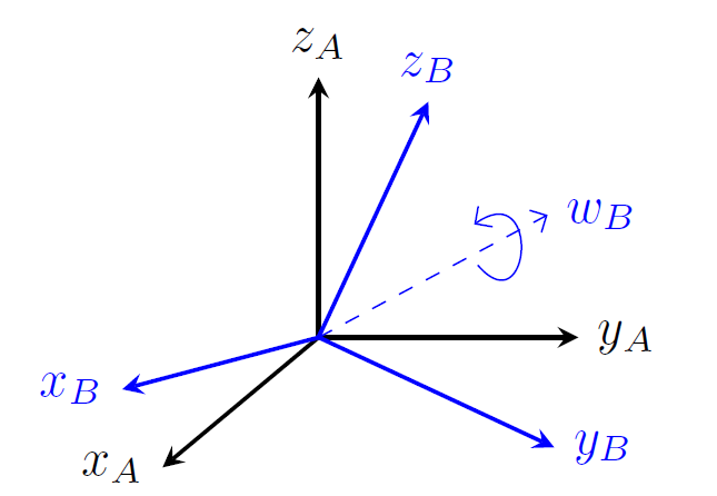
In Equation \(\eqref{eq:RotMatDot}\), \(S(t)\) represents an angular velocity vector. Therefore, the specific physical interpretation of \(S(t)\) is determined by the reference frame in which this vector is defined. Consider two reference frames, \(A\) and \(B\), in three-dimensional space (refer to Figure 2). Assume that the origins of the two frames coincide. Suppose frame \(A\) is stationary, while frame \(B\) is undergoing rotation. In this context, \(\bmatrix{R}^{BA} \in \mathbb{R}^{3\times3}\) signifies the rotation matrix from frame \(A\) to frame \(B\). The time derivative of the rotation matrix \(\bmatrix{R}^{BA}\) is expressed as:
