Pitch Actuator Dynamics
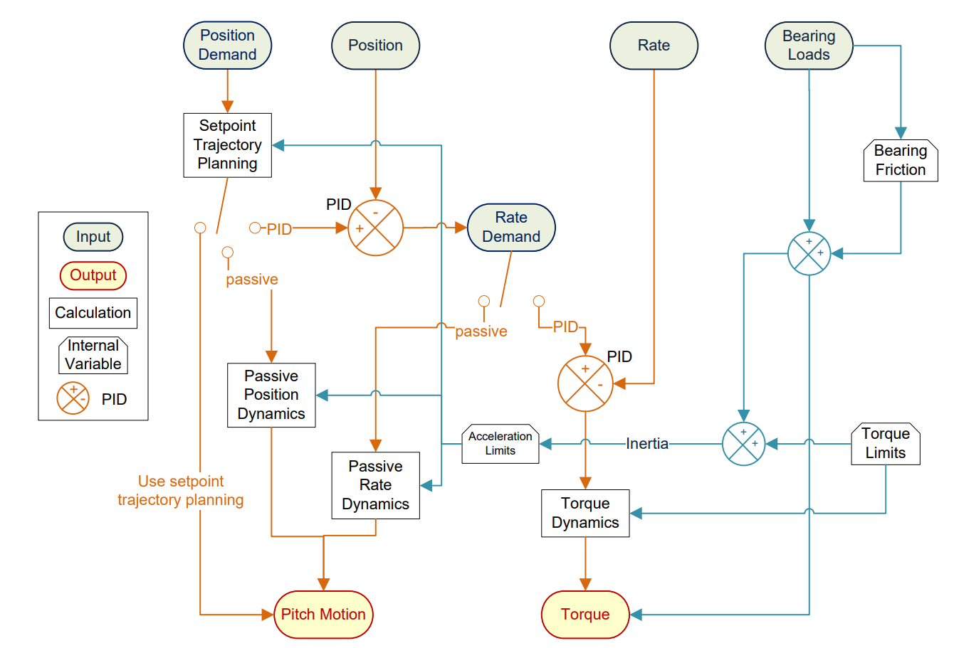
The pitch actuator may be modelled as either a pitch position or pitch rate actuator, and the demand type coming from the controller must match the input demand type specified in the pitch actuator definition. This section describes the theory behind the features in the pitch actuator definition. An illustration of the pitch actuator algorithm is given in Figure 1, which provides an overall picture of the pitch actuator algorithm from the passive pitch response to the active pitch response.
Set point trajectory planning
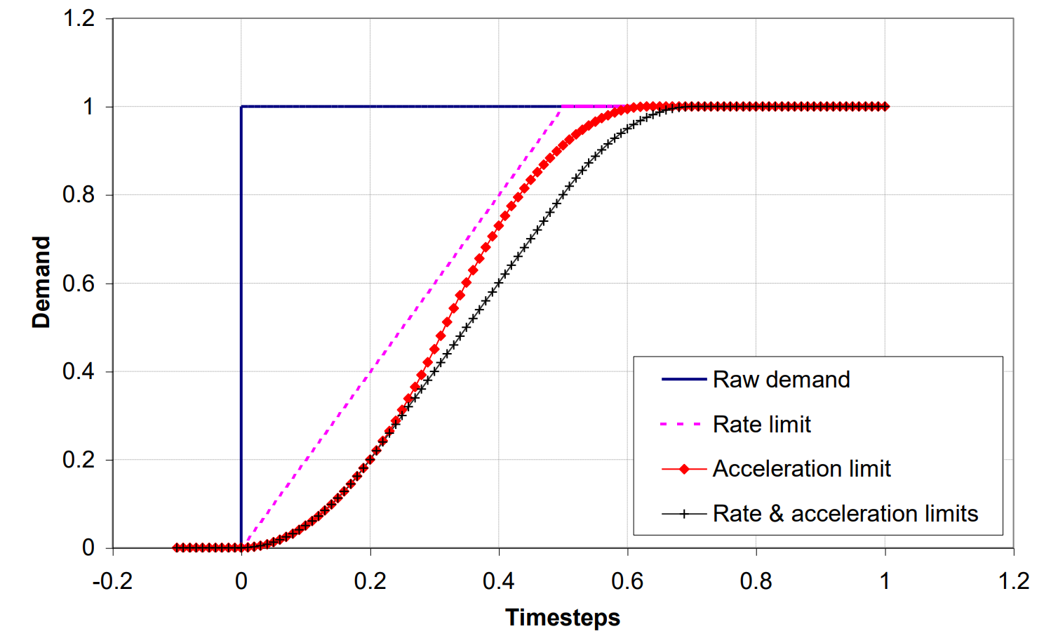
The set point trajectory planning (also known as ramp control) enables step changes in demand coming from a discrete controller to be smoothed according to rate and acceleration limits. The limits will also limit the controller demand over many controller time-steps meaning that if the set point trajectory limits are within the controller limits, the pitch demand will be further limited. This functionality is illustrated in Figure 2.
Passive response
In a passive model, the passive dynamics are represented by a Laplace transfer function. If the input is position demand, then the transfer function takes an input of position demand, and the output is the pitch angle of the Blade. If the input is rate demand, then the output of the transfer function is the blade pitch rate.
In the following equations, \(u\) represents the input and \(x\) represents the output. The equation of motion and corresponding Laplace transfer function representations are shown in Table 1.
representation.
| Equation of motion | Laplace Transfer Function Representation | |
|---|---|---|
| 1st order (\(\tau\) = lag time) | \(\tau\frac{dx(t)}{dt} + x(t) = u(t)\) | \(H(s) = \frac{\frac{1}{\tau}}{\frac{1}{\tau} + s}\) |
| 2nd order (\(\omega\) = frequency, \(\zeta\) = damping ratio) | \(\frac{d^{2}x(t)}{dt} + 2\zeta\omega\frac{dx(t)}{dt} + \omega^{2}x = \omega^{2}u(t)\) | \(H(s) = \frac{\omega^{2}}{\omega^{2} + 2\zeta\omega s + s^{2}}\) |
The output from the transfer function is used to prescribe the pitch structural freedom. In order to do this, the acceleration must be obtained so that inertial loads are included in the structural loads and so that pitch torque can be calculated. With a 1st order transfer function, it is not possible to calculate the second derivative of the output, and because of this a 1st order response to position demand is approximated by a 2nd order transfer function. This is done by multiplying the 1st order transfer function by another 1st order transfer function with a time lag a tenth of the user-defined time lag.
The state representation of the transfer function may be of interest to the user. Based on single-input, single-output linear state-space model, the states are represented in controllable canonical form such that (where \(\bvector{x} = \bvector{x}(t)\) represents the state vector, \(\bvector{u} = \bvector{u}(t)\) the input vector and \(\bvector{y} = \bvector{y}(t)\) the output vector):
With a general transfer function notated by:
The matrices \(\mathbf{A}\), \(\mathbf{B}\) and \(\mathbf{C}\) take the form:
The response to position or rate demand may also be chosen to use the set point trajectory planning definition. This means that the pitch motion is equal to the output of set point trajectory planning (i.e. the limited demand). This may only be done if the set point trajectory planning acceleration limits have been defined so that the inertial loads of the structural model are taken into account.
Active response PID
The user can select a continuous time PID closed loop control response to simulate position/rate input and force/torque output pitch control. With a rate demand input, a closed loop PID algorithm produces a torque or force demand depending on the type of actuator drive chosen. With a position demand input, a closed loop PID algorithm produces a rate demand as output. With a rate demand input, a closed loop PID algorithm produces a torque or force demand depending on the type of actuator drive chosen. The options for the PID algorithm are described in PI control algorithm for wind turbines. This functionality is illustrated in Figure 1.
Position limits
Two types of position limits may be defined. The conditions for tripping and un-tripping of limit switches are defined in Table 2.
| Limit switch | Input demand | |
|---|---|---|
| Position | Rate | |
| Trips | Pitch position is beyond limit switch and position demand is beyond limit switch | Pitch position is beyond limit switch and rate demand is away from the region between the limit switch positions |
| Un-trips | Position demand is in the region between the limit switch positions | Rate demand is towards the region between the limit switch positions |
When the limit switch is tripped, the actuator torque or force is cut so that the only load coming from the drive is the motor inertial load. The pitch brake is also applied. If the brake has not been defined then the model internally applies a friction torque to bring the blade to a stop. If the brake is defined as too strong, then Bladed internally limits the deceleration of the blade. This is to avoid numerical instabilities occurring when the brake is applied.
The end-stops are implemented as a simple stiffness model, with no damping. The torque provided by the end-stop is therefore:
Actuator drives
Rotary actuator
A rotary actuator drive models a system of a pitch motor and a gear ratio, see Figure 3. The motor rotational inertia is represented about the pitch axis but defined on the motor side of the gear ratio. The brake is also defined on the motor side of the gear ratio. When this is applied, the brake torque applies a kinetic friction and also, when the pitch structural freedom is stuck, a 'stiction' of equal value to the kinetic friction. The transfer functions for torque response are defined the same as for response to position and rate demand. If the instantaneous response to torque demand is chosen, the torque demand is converted directly into an actuator torque. The governing equation for a rigid rotary actuator is for a passive case:
where \(Q_{\text{act}}\) is the actuator torque, \(I_{\text{motor}}\) the motor rotational inertia, \(\alpha_{\text{ring}}\) the pitch acceleration, \(R\) the gear ratio, \(\eta\) the motor efficiency, \(Q_{\text{ext}}\) the external bearing moment (which is equivalent to Blade (root axes) \(M_Z\) at the root), and \(Q_{\text{fric}}\) the bearing friction.
However, in an active case, Bladed is unable to apply an efficiency to the torque at the pinion. This is due to the potentially rapidly changing accelerations of the system and difficulties of numerical modelling. This means that the efficiency can only be applied to the actuator torque, which results in the equation:
The flexibility on the high speed shaft (motor side of the gear ratio) is only available for the Rotary actuator drive, and the torque output option (Closed loop PI(D)) under Actuator dynamic response must be selected. It is modelled as a single degree of freedom torsional spring-damper system, and the parameters for the flexibility is defined on the motor side of the gearing.
Linear actuator
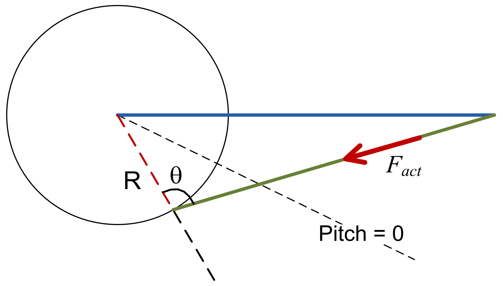
A linear actuator drive models a system where linear force via a ram is converted into a torque on the bearing, see Figure 4. The principal equation governing the drive is:
where \(F_{\text{act}}\) is the actuator force, \(R\) the radius to connection point, \(\theta\) the angle between radius to connection point and ram, \(Q_{\text{ext}}\) the external bearing moment, and \(Q_{\text{fric}}\) the bearing friction.
Pitch bearing friction
The pitch bearing kinetic friction torque is modelled as the sum of four terms: a constant, a term dependent on the bending moment at the bearing, and a term dependent on the magnitude of the axial and radial forces on the bearing. Sometimes the actuator cannot overcome the applied torques and the pitch motion will stick. Before it can move again, the break-out or 'stiction' torque must be overcome. This is modelled as an additional contribution to the friction torque while the pitch is not moving. This additional contribution is specified as a constant torque, plus a term dependent on the kinetic friction torque.
The functions \(f_{1}\), \(f_{2}\), \(f_{3}\), \(f_{4}\) can be defined in two forms. They may be defined as proportional to the load argument or they may be defined as a lookup table based on the argument load.


