Introduction
This section provides an introduction into the general theory of control algorithm adopted by Bladed for various sub-systems including the control system, pitch actuator and LIDAR. The description starts with a brief overview into the basic of proportional-integral (PI) control algorithm which is commonly adopted in wind turbine operations in PI control algorithm for wind turbines. Then, further details about the power production control strategy are given in Power production control, followed by the Pitch actuator dynamics.
PI control algorithm for wind turbines
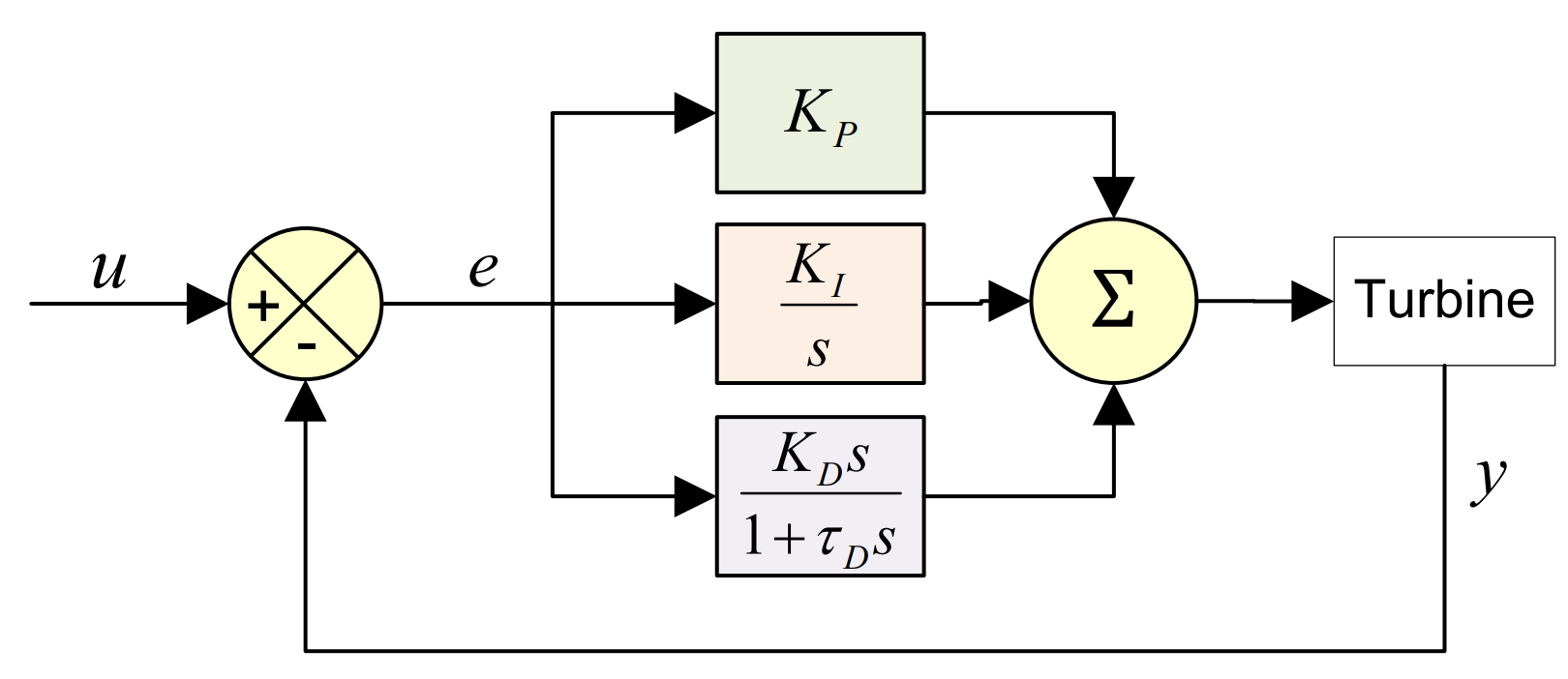
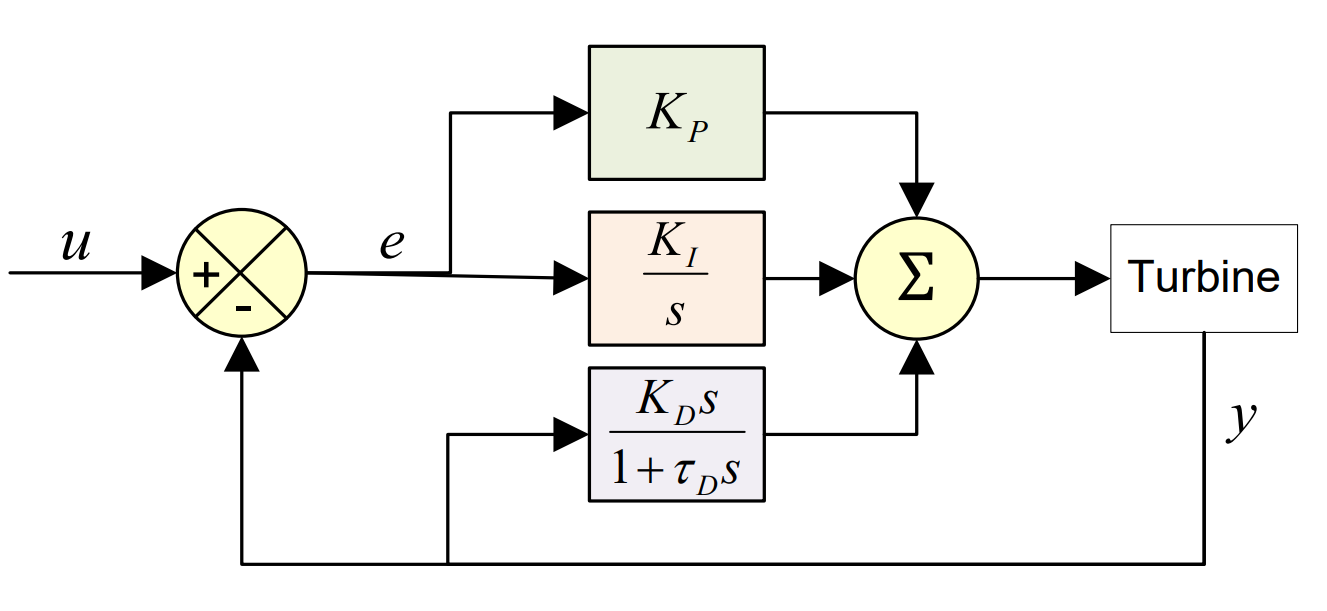
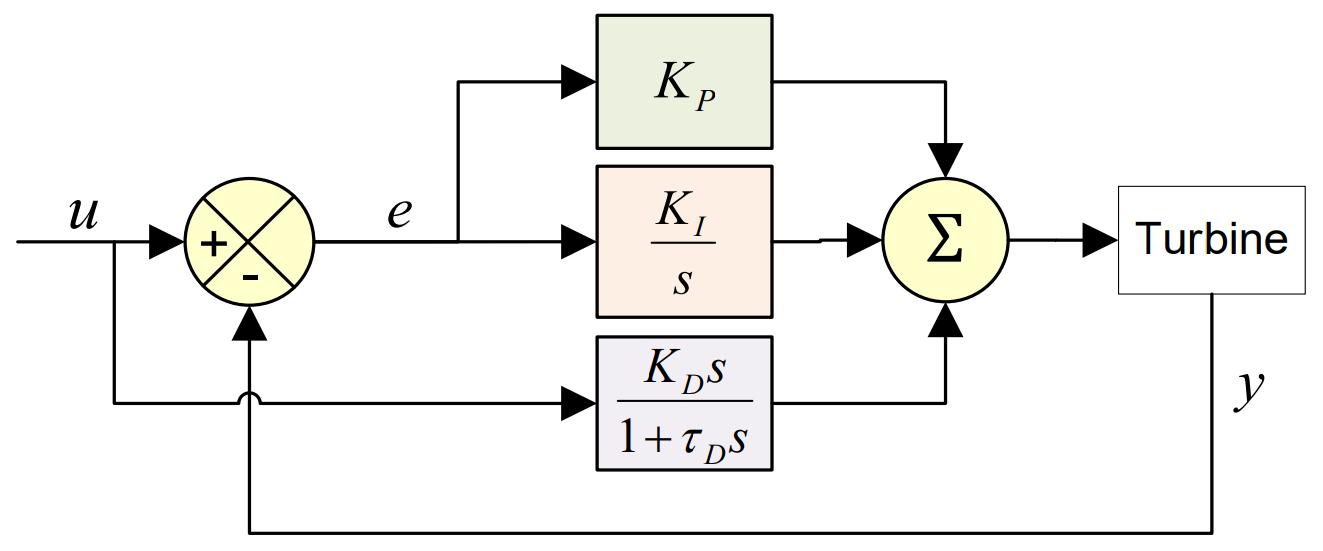
The output of the PI algorithms in Bladed is represented by the following equations (see also illustrations in Figure 1, Figure 2 and Figure 3):
with \(K_{P}\) = proportional gain, \(K_{I}\) = integral gain, \(K_{D}\) = derivative gain, \(e\) = input error signal.
In reality, the derivative term never directly acts on the error term as this produces a very noisy signal, particularly when there are large changes in input signal. This means that the input (\(e'\)) for the derivative term must be filtered by a 1st order time lag \(\tau_{D}\). The derivative term input signal can be the error as for the proportional and integral terms or can be the set point or feedback \(y\). The equations corresponding to these different approaches are provided below and in Figure 1.
Derivative action equations depending
Calculation of appropriate values for the gains is a specialist task, which should take into account the dynamics of the turbine together with the aerodynamic characteristics and principal forcing frequencies, and should aim to achieve stable control at all operating points and a suitable trade-off between accuracy of tracking the set-point, reduction in loading and the degree of actuator activity.
Straightforward implementation of the above equations leads to the problem of ‘integrator wind-up’ if the output \(y(t)\) is subject to limits, as is the case here. This means that the raw output calculated as above continues to change as a result of the integral (\(K_{I}\)) term even though the actual output is being constrained to a limit. When the direction of movement of \(y(t)\) changes, it will then take a long time before it comes back to the limit so that the final (constrained) output starts to change. This is avoided in the continuous-time implementation of the PI controller by an additional term \(-\Delta y/T_{d}\) in the above equation, where \(\Delta y\) is the amount by which the raw output \(\ y(t)\) has gone beyond the limit, and \(T_{d}\) is the desaturation time constant which must be supplied by the user.


Gain scheduling algorithm
Since the characteristics of the turbine, especially the aerodynamic characteristics, are not constant but will vary according to the operating point, and hence the wind speed, it may be necessary to adjust the controller gains as a function of the operating point in order to ensure that suitable control loop characteristics are achieved at all wind speeds. This is known as gain scheduling, and the gain scheduling model provided in Bladed allows both the proportional and integral gains of any control loop to be scaled by a factor \(1/F\), where \(F\) is a function of some variable \(V\) which is accessible to the controller and which is representative of the operating point in some way.
The choices available are:
- \(F\) = constant
- \(F = F(V)\) as defined by a lookup table
The choice of variable \(V\) depends on the particular control loop. The following choices are provided:
Fixed speed pitch regulated controller:
- Electrical power, pitch angle, wind speed.
Variable speed below-rated torque controller:
- Electrical power, generator speed, wind speed, and pitch angle (in the pitch regulated case).
Variable speed stall regulated above-rated controller:
- Electrical power, generator speed, wind speed.
Variable speed pitch regulated above-rated controller:
- Electrical power, generator speed, wind speed, pitch angle.
The variables shown in bold are normally recommended. Gain scheduling is unlikely to be required for the variable speed below rated controllers. For the variable speed stall regulated above-rated controller, no general rule can be given. Gain scheduling on wind speed is not usually a practical proposition because of the difficulty of measuring a representative wind speed, and this option is only provided for research purposes. The wind speed used is the hub wind speed, which may differ from any wind speed measured by an anemometer instrument mounted on the nacelle, especially in the case of an upwind stream turbine.
Gain scheduling on pitch angle is recommended for the pitch regulation controllers, to compensate for the large changes in the sensitivity of aerodynamic torque to pitch angle over the operating range. The steady loads calculation may be used to calculate the partial derivative of aerodynamic torque with respect to pitch angle, and F may be set proportional to this. In many cases, simply setting F proportional to pitch angle is a good approximation, but a lower limit for F must be set to prevent excessive gains at small pitch angles.
Optimal tip speed ratio tracking
Below rated wind speed, a variable speed turbine may try to stay at its optimum tip speed ratio wherever possible, by changing the rotor speed in proportion to the wind speed. This maximises the power coefficient and hence the aerodynamic power available.
This can be achieved in the steady state by setting the generator torque to be proportional to the square of the rotor or generator speed. The Optimal mode gain multiplies the square of the generator speed to give the required generator torque demand. It can be calculated as:
where:
- \(K_{opt}\) is the Optimal mode gain,
- \(\rho\) is the air density,
- \(R\) is the rotor radius,
- \(C_p\) is the power coefficient at \(\lambda\)
- \(\lambda\) is the desired tip speed ratio
- \(G\) is the gearbox ratio
The torque demand is then given by:
where \(Q_d\) is the demanded generator torque and \(\omega_g\) is the measured generator speed.
Note that energy output may not be maximised by maximising aerodynamic efficiency, because the energy losses may also vary with the operating point. It may therefore be better to track a slightly different tip speed ratio. The desired tip speed ratio and the corresponding power coefficient should be used in calculating the Optimal mode gain as above. Alternatively, the torque-speed curve may be expressed as a lookup table to account for losses or any other effects.