Power Production Control
Closed loop control may be used during normal running of the turbine to control the blade pitch angle and, for variable speed turbines, the rotor speed. Four different controller types are provided:
Fixed speed stall regulated. The generator is directly connected to a constant frequency grid, and there is no active aerodynamic control during normal power production.
Fixed speed pitch regulated. The generator is directly connected to a constant frequency grid, and pitch control is used to regulate power in high wind velocities.
Variable speed stall regulated. A frequency converter decouples the generator from the grid, allowing the rotor speed to be varied by controlling the generator reaction torque. In high wind velocities, this speed control capability is used to slow the rotor down until aerodynamic stall limits the power to the desired level.
Variable speed pitch regulated. A frequency converter decouples the generator from the grid, allowing the rotor speed to be varied by controlling the generator reaction torque. In high wind velocities, the torque is held at the rated level and pitch control is used to regulate the rotor speed and hence also the power.
For a constant speed stall regulated turbine no parameters need be defined as there is no control action. In the other cases the control action will determine the steady state operating point of the turbine as well as its dynamic response. For steady state calculations it is only necessary to specify those parameters which define the operating curve of the turbine. For dynamic calculations, further parameters are used to define the dynamics of the closed loop control. The parameters required are defined further in the following sections.
Note that all closed loop control data are defined relative to the high speed shaft.
The fixed speed pitch regulated controller
This controller is applicable to a turbine with a directly-connected generator which uses blade pitch control to regulate power in high wind velocities. It is applicable to full or partial span pitch control, as well as to other forms of aerodynamic control such as flaps or ailerons. In the latter case, the pitch angle can be taken to refer to the deployment angle of the flap or aileron.
From the optimum position, the blades may pitch in either direction to reduce the aerodynamic torque. If feathering pitch action is selected, the pitch-able part of the blade moves to reduce its angle of attack as the wind speed (and hence the power) increases. If stalling pitch action is selected, it moves in the opposite direction to stall the blade as the wind speed increases. In the feathering case, the minimum pitch angle defines the pitch setting below rated, while in the stalling case the maximum pitch angle is used below rated, and the pitch decreases towards the minimum value (usually a negative pitch angle) above rated.
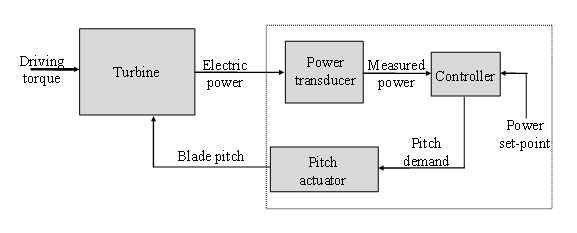
Figure 1 shows schematically the elements of the fixed speed pitch regulated control loop which are modelled.
FSPR Steady state parameters
In order to define the steady-state operating curve, it is necessary to define the power set-point and the minimum and maximum pitch angle settings, as well as the direction of pitching as described above. The correct pitch angle can then be calculated in order to achieve the set-point power at any given steady wind speed.
FSPR Dynamic parameters
To calculate the dynamic behaviour of the control loop, it is necessary to specify the dynamic response of the power transducer and the pitch actuator, as well as the actual algorithm used by the controller to calculate a pitch demand in response to the measured power signal.
The variable speed stall regulated controller
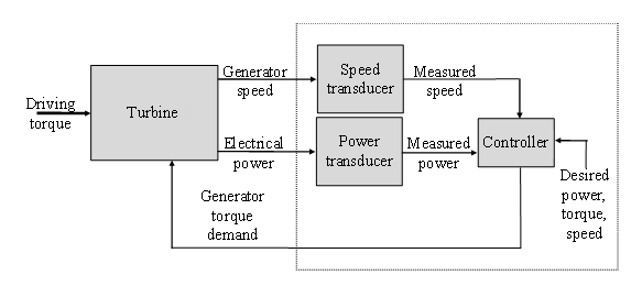
This controller model is appropriate to variable speed turbines which employ a frequency converter to decouple the generator speed from the fixed frequency of the grid, and which do not use pitch control to limit the power above rated wind speed. Instead, the generator reaction torque is controlled so as to slow the rotor down into stall in high wind speeds. The control loop is shown schematically in Figure 2.
VSSR Steady state parameters
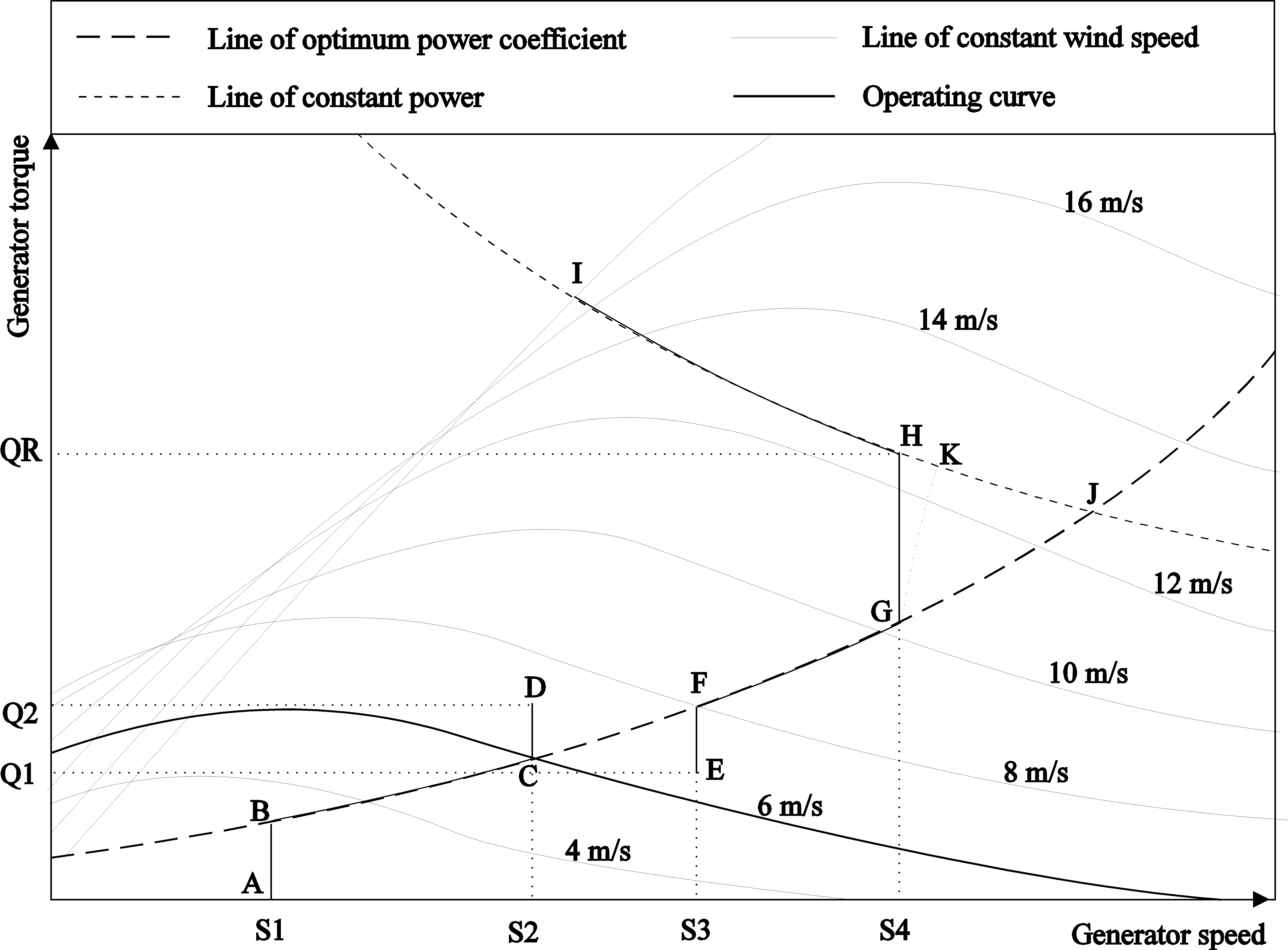
The steady-state operating curve can be described with reference to a torque-speed graph as in Figure 3. (for a wind turbine, but the same principles apply to tidal turbines). The allowable speed range in the steady state is from S1 to S2. In low winds it is possible to maximise energy capture by following a constant tip speed ratio load line which corresponds to operation at the maximum power coefficient. This load line is a quadratic curve on the torque-speed plane, shown by the line BG in Figure 3. Alternatively, a lookup table may be specified.
If there is a minimum allowed operating speed S1, then it is no longer possible to follow this curve in very low winds, and the turbine is then operated at nominally constant speed along the line AB shown in the figure. Similarly in high wind speeds, once the maximum operating speed S4 is reached, then once again it is necessary to depart from the optimum load line by operating at nominally constant speed along the line GH.
Once maximum power is reached at point H, it is necessary to slow the rotor speed down into stall, along the constant power line HI. If high rotational speeds are allowed, it is of course possible for the line GH to collapse so that the constant power line and the constant tip speed ratio line meet at point J.
Clearly the parameters needed to specify the steady state operating curve are:
The minimum speed, S1
The maximum speed in constant tip speed ratio mode, S4
The maximum steady-state operating speed. This is usually S4, but could conceivably be higher in the case of a turbine whose characteristics are such that as the wind speed increases, the above rated operating point moves from H to I, then drops back to H,and then carries on (towards J) in very high winds. This situation is somewhat unlikely however, because if rotational speeds beyond S4 are permitted in very high winds, there is little reason not to increase S4 and allow the same high rotor speeds in lower winds.
The above rated power set-point, corresponding to the line HI. This is defined in terms of shaft power. Electrical power will of course be lower if electrical losses are modelled.
The parameter \(K_{opt}\) is the optimal mode gain which defines the constant tip speed ratio line BG.
Then when the generator torque demand is set to \(K_{opt} \omega^2\) where \(\omega\) is the measured generator speed, this ensures that in the steady state the turbine will maintain tip speed ratio \(\lambda\) and the corresponding power coefficient \(C_p(λ)\). Note that power train losses may vary with rotational speed, in which case the optimum rotor speed is not necessarily that which results in the maximum aerodynamic power coefficient.
As an alternative to the constant parameter \(K_{opt}\), a lookup table may be specified giving generator torque as a function of generator speed.
VSSR Dynamic parameters
To calculate the dynamic behaviour of the control loop, it is necessary to specify the dynamic response of both power and speed transducers, as well as the actual algorithm used by the controller to calculate a generator torque demand in response to the measured power and speed signals.
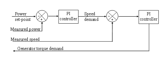
Two closed loop control loops are used for the generator torque control, as shown in Figure 4. An inner control loop calculates a generator torque demand as a function of generator speed error, while an outer loop calculates a generator speed demand as a function of power error.
Below rated, the speed set-point switches between S1 and S4. In low winds it is at S1, and the torque demand output is limited to a maximum value given by the optimal tip speed ratio curve BG. This causes the operating point to track the trajectory ABG. In higher winds, the set-point changes to S4, and the torque demand output is limited to a minimum value given by the optimal tip speed ratio curve, causing the operating point to track the trajectory BGH. Once the torque reaches QR, the outer control loop causes the speed set-point to reduce along HI, and the inner loop tracks this varying speed demand.
The variable speed pitch regulated controller
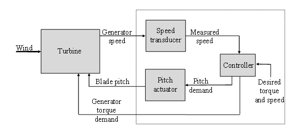
This controller model is appropriate to variable speed turbines, which employ a frequency converter to decouple the generator speed from the fixed frequency of the grid, and which use pitch control to limit the power above rated wind speed. The control loop is shown schematically in Figure 5.
Steady state parameters
The steady-state operating curve can be described with reference to the torque-speed graph shown in Figure 6. Below rated, i.e. from point A to point H, the operating curve is exactly as in the stall regulated variable speed case described in Figure 3. Above rated however, the blade pitch is adjusted to maintain the chosen operating point, designated L. Effectively, changing the pitch alters the lines of constant wind speed, forcing them to pass through the desired operating point.
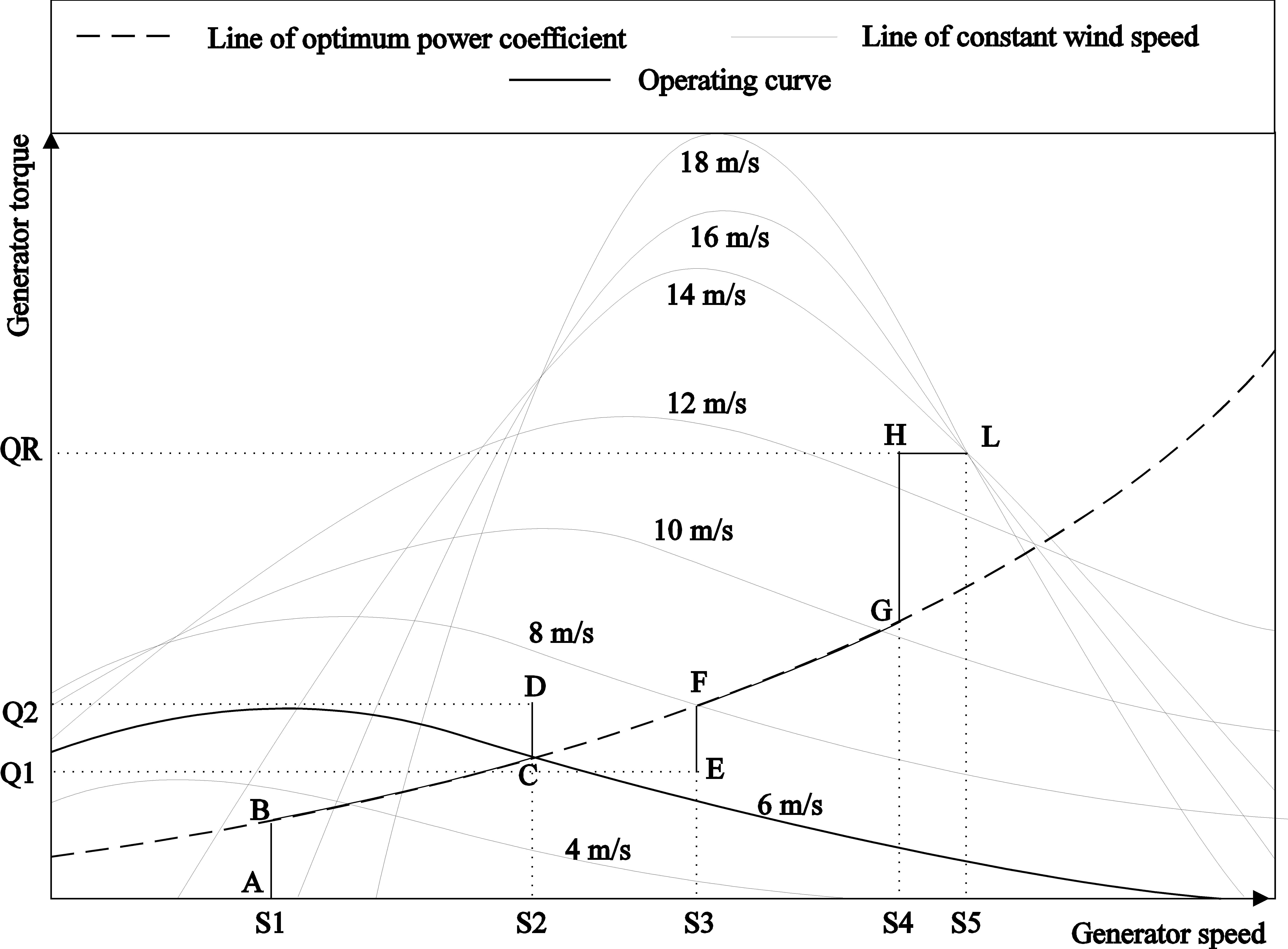
Once rated torque is reached at point H, the torque demand is kept constant for all higher wind speeds, and pitch control regulates the rotor speed. A small (optional) margin is allowed between points H (where the torque reaches maximum) and L (where pitch control begins) to prevent excessive mode switching between below and above rated control modes. However, this margin may not be required, in which case points H and L coincide. As with the stall regulated controller, the line GH may collapse to a point if desired.
Clearly the parameters needed to specify the steady state operating curve are:
- The minimum speed, S1
- The maximum speed in constant tip speed ratio mode, S4
- The speed set-point above rated (S5). This may be the same as S4.
- The maximum steady-state operating speed. This is normally the same as S5.
- The above rated torque set-point, QR.
- The parameter \(K_{opt}\) which defines the constant tip speed ratio line BG, or a lookup table. Please see optimal mode gain for more details.
Dynamic parameters
To calculate the dynamic behaviour of the control loop, it is necessary to specify the dynamic response of the speed transducer and the pitch actuator, as well as the actual algorithm used by the controller to calculate the pitch and generator torque demands in response to the measured speed signal.
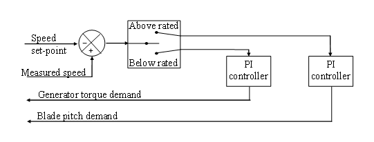
Figure 7 shows the control loops used to generate pitch and torque demands. The torque demand loop is active below rated, and the pitch demand loop above rated.
Below rated, the speed set-point switches between S1 and S4. In low winds it is at S1, and the torque demand output is limited to a maximum value given by the optimal tip speed ratio curve BG. This causes the operating point to track the trajectory ABG. In higher winds, the set-point changes to S4, and the torque demand output is limited to a minimum value given by the optimal tip speed ratio curve, causing the operating point to track the trajectory BGH, and a maximum value of QR. When point H is reached the torque remains constant, with the pitch control loop becoming active when the speed exceeds S5.
Control mode changes
The variable speed controllers, both stall regulated and pitch regulated, require the following mode changes:
- Change of speed set-point from S1 to S4 (refer to Figure 2 and Figure 5). This occurs when the measured speed crosses the threshold value (S1+S4)/2. This mode change is completely benign as the control action along the optimum tip speed ratio line BG is the same either side of the mode change point, so no hysteresis is required.
- Change from below rated to above rated control.
For the stall regulated case, the change from below rated to above rated is also benign. Making the switch in the middle of the section GH of Figure Figure 2 causes no immediate change in control action. However, in the case of G and H coinciding, or being very close together, it may be necessary to modify the mode change strategy, depending on the turbine characteristics.
For the pitch regulated case, the change to above rated control occurs when the torque demand is at maximum (QR) and the speed exceeds S5 (refer to Figure 5). The change to below rated occurs when the pitch demand is at fine pitch (minimum pitch for the feathering case, maximum pitch for pitch-assisted stall) and the speed falls below S4. While this strategy is usually suitable, it may be desirable to modify it depending on the turbine characteristics.