Design a simplified blade for aerodynamics in JSON
Summary
In this tutorial, we aim to show you how to take advantage of the wide range of default input values assumed by the JSON schema when you omit those parameters from your input file.
Prerequisites
- Latest version of Bladed Next Gen and Samples installed including the Bladed Python packages.
- Licence for Bladed Next Gen (request a licence).
- Bladed Results Viewer.
We would recommend opening the samples folder in VS Code to follow along with these tutorials.
If you do not yet know how to run a simulation, please follow the instructions and checks in the Get started and Run a simulation tutorials before continuing.
It might be advisable to read through the Blade Coordinate Systems article in the modelling section of the documentation before completing this tutorial.
Subjects covered
By the end of this tutorial you should have:
- An understanding of the default behaviour of the Blade component when you omit several of its options and geometric parameters.
- Model a fully rigid blade.
- Understand how the reference coordinates work.
- Model an aerodynamic only planform blade.
- Interpolate a set of aerofoils along the blade span.
- Remove all superfluous components.
- Compare the results of a complex fully modelled rigid blade versus a blade simplified with default inputs.
Sample deck
To follow this example we advise that you pick up the sample file demo_a_pcoeffs.json from the samples package available for download in this website.
Given the low level of detail that can be present in this type of early design, a performance coefficient simulation type is chosen. This would allow for fast iterations and manual design of the plan shape of the blade without concerning with too much details to start with. Our aim here is speed of design over accuracy.
The resulting simplified input file can also be downloaded as part of the samples package and is named planform_demo_a_pcoeffs.json. We advise that you compare both files side by side as you follow this tutorial.
Design wind speed optimal blade shape
The first assumption we are going to make is that we are designing the blade operating at it's intended wind speed (usually between \(7.5m/s\) and \(8m/s\)) and that at these conditions the blade should have no changes in shape due to the aerodynamic loads. This is because those loads will be corrected later during the manufacturing by forcing pre-bend, pre-sweep and pre-twist as needed to achieve an optimal surface at this same design wind speed. You might choose to use all or just a few of the following default behaviors depending on the complexity you want at different design stages.
Default mounting settings
In the blade definition you can explicitly provide a coning and sweep angle that will be applied to the root of the blade where it is mounted on the hub. Here the defaults of both angles are \(0 rad\) and the entire Mounting property can be removed. For more details on this property check the Blade Coordinate Systems article in the modelling section of the documentation.
{
  ...
  "ComponentDefinitions":{
    "Blade":{
    "ComponentType": "Blade",
      ...
-     "Mounting": {
-       "ConingAngle": 0.0,
-       "SweepAngle": 0.0
-       },
+     "_comment": "The mounting has been removed to assume no sweep nor coning",
    }
    ...
  }
}
Modelling a rigid blade
With a performance coefficient simulation you will be focusing on aerodynamic design regardless of the structures of the blade, while you try to aim for the optimum shape to maximum power at design wind speed.
In such a situation the blade will be considered fully rigid, and Damping, MassProperties and StructuralProperties definitions are superfluous.
The first thing to do is to change the blade modelling type to fully rigid:
{
  ...
  "ComponentDefinitions": {
    "Blade": {
      "ComponentType": "Blade",
      "Modelling": {
+       "BladeModellingType":"RigidBladeModelling"
-       "BladeModellingType": "ModalBladeModelling",
-       "WholeBladeModeDampingRatios": [
-         {
-           "DampingRatio": 0.01
-         },
-         {
-           "DampingRatio": 0.01
-         },
-         {
-           "DampingRatio": 0.01
-         },
-         {
-           "DampingRatio": 0.01
-         }
-       ],
-       "NumberOfModesPerBladePart": 4,
-       "GeometricStiffnessModel": "AxialLoadsOnly",
-       "IgnoreAxesOrientationDifferencesForShear": false
      },
      ...
    }
  }
}
Once this is done the MassProperties and StructuralProperties are ignored in each of the blade sections and can also be removed. Here we only give the example of a single section, but the sample file has these properties removed from every single blade section.
{
  ...
  "ComponentDefinitions": {
    "Blade": {
      "ComponentType": "Blade",
      "SectionDefinitions": [
        {
          ...
+         "_comment": "StructuralProperties and MassProperties are removed to model a rigid blade",
-         "StructuralProperties": {
-           "BendingStiffnessAboutX": 2607000000.0,
-           "BendingStiffnessAboutY": 2433000000.0
-         },
          "AerodynamicProperties": {
            "Chord": 2.06667,
            "ThicknessToChordRatio": 1.0,
            "AerodynamicSection": "demo_cyl"
          },
-         "MassProperties": {
-           "MassPerUnitLength": 369.809,
-           "MomentOfInertia": 0.0,
-           "RadiusOfGyrationRatio": 1.0
-         }
        },
        ...
    },
    ...
  }
}
For a reference on aerodynamic properties, structural properties and mass properties please check the respective articles in the Bladed Next Gen modelling section of the documentation.
Single reference coordinate system aligned with the blade root origin
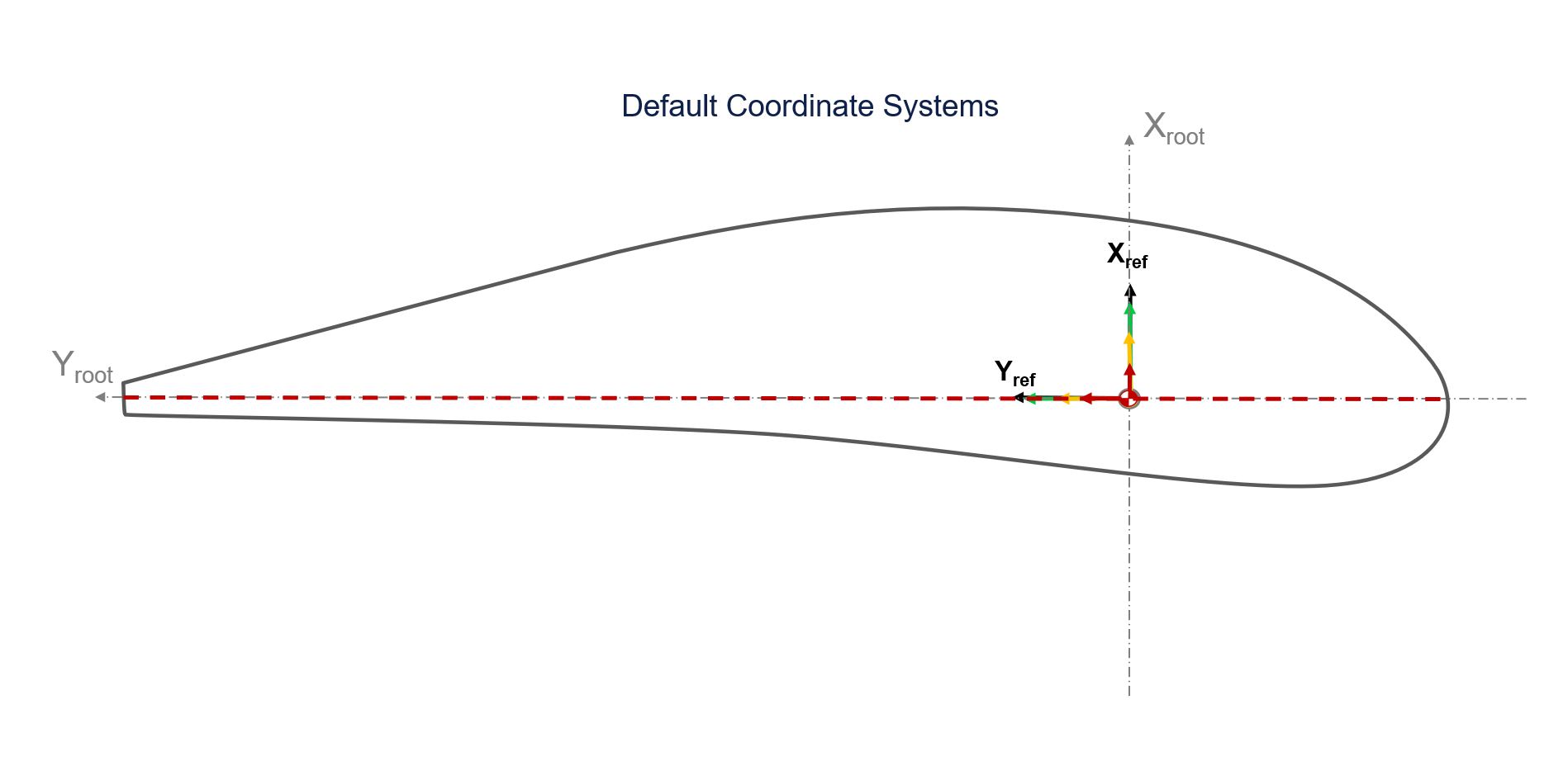
When defining a planform rigid blade for aerodynamic design, all the aerofoils are ideally oriented towards the inflow wind. Their 3-dimensional location within a specific section will not change the output power. Only the orientation of the wind as a function of the rotation speed at the section and the atmospheric boundary layer wind speed at the height of the section will change the loads on the blade. Therefore the only important spacial parameters that we need to define for an aerofoil are its orientation with respect to the root coordinate system (section twist angle) and the DistanceAlongSpan from the blade root origin point.
All section specific coordinate systems that depend on the default to being coincident with the ReferenceCoordinateSystem of each section.
{
  ...
  "ComponentDefinitions": {
    "Blade": {
      "ComponentType": "Blade",
      ...
      "SectionDefinitions": [
        {
-           "IsBladePartBoundaryAtThisSection": false,
            "AxesAndCoordinateSystems": {
                "ReferenceCoordinateSystem": {
                "Origin": {
                    "X": 0.0,
                    "Y": 0.0,
                    "DistanceAlongSpan": 3.44444
                },
                "ZAxis": {
                    "X": 0.0,
                    "Y": 0.0,
                    "Z": 1.0
                },
                "YAxis": {
                    "X": 0.0,
                    "Y": 1.0,
                    "Z": 0.0
                }
-              },
-              "NeutralAxisCoordinateSystem": {
-                "RotationAboutReferenceZ": -0.157079502940178,
-                "OffsetInReferenceX": 0.0,
-                "OffsetInReferenceY": 0.0
-              },
-              "QuarterChordCoordinateSystem": {
-                "RotationAboutReferenceZ": -0.157079502940179,
-                "OffsetInReferenceX": -0.0560383445786268,
-                "OffsetInReferenceY": -0.353812480056145
-              },
-              "MassCoordinateSystem": {
-                "RotationAboutReferenceZ": -0.157079502940178,
-                "OffsetInReferenceX": 0.0126135201346769,
-                "OffsetInReferenceY": -0.00302809912168379
-              },
-              "ShearAxis": {
-               "OffsetInReferenceX": -0.163804391845216,
-               "OffsetInReferenceY": -1.03422109554873
                }
            },
        ...
        }
      ],
      ...
    }
  }
}
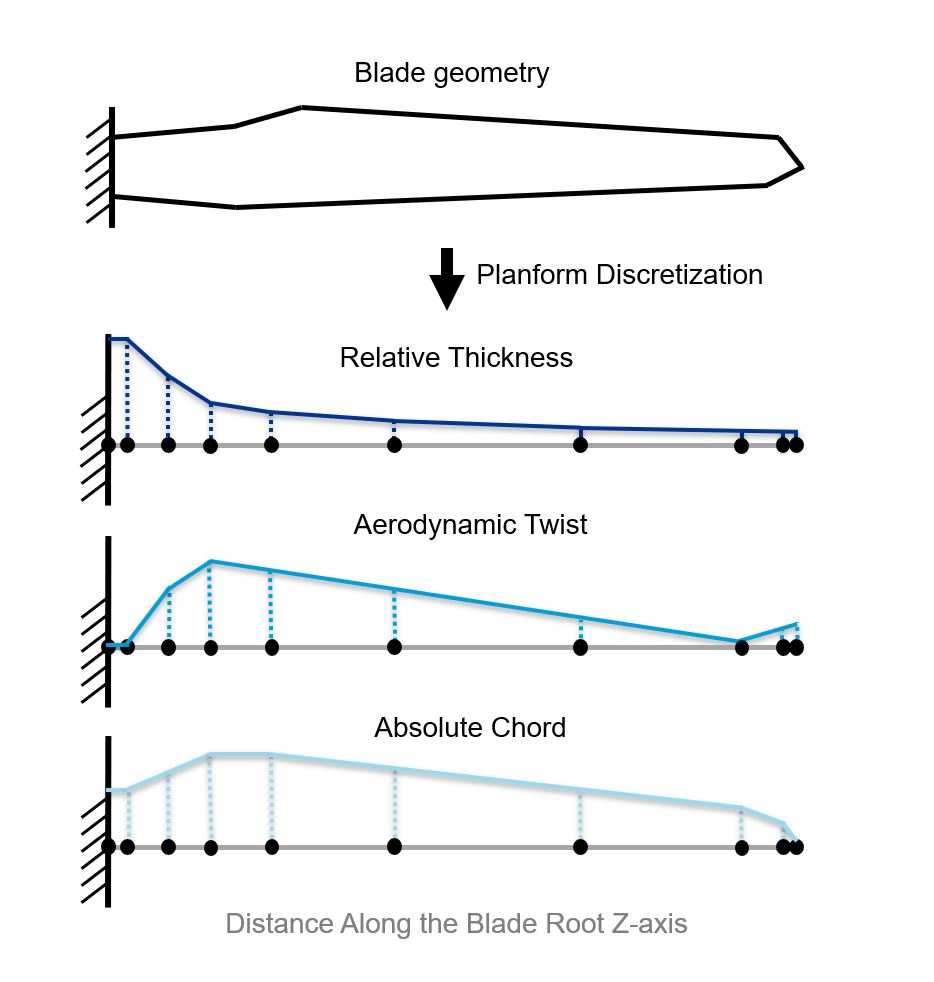
Blade basic geometry: span, chord, relative thickness and twist
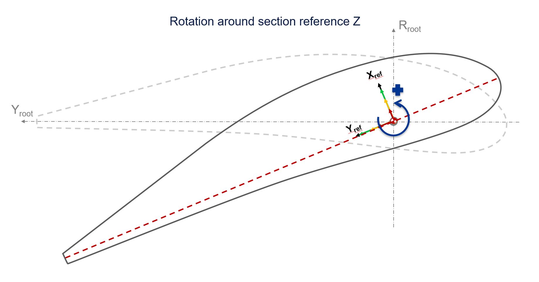
We can model the location of the sections and the twist using only the ReferenceCoordinateSystem, and have a blade definition that only uses as inputs the DistanceAlongSpan, Chord, ThicknessToChordRatio and twist (RotationAboutReferenceZ which is positive rotating the aerofoil nose up).
Warning
The RotationAboutReferenceZ follows the right hand rule and therefore has an opposite direction of rotation from the Bladed 4.x twist. You can check more about this rotation convention in the Bladed Next Gen manual's Blade Coordinate Systems article.
RotationAboutReferenceZ replacing the twist.The aerodynamic coordinate system named QuarterChordCoordinateSystem is where usually the aerodynamic twist would be defined. However, since this reference frame defaults to coincide with the ReferenceCoordinateSystem, both reference systems will rotate together, and in the simplest form of defining the blade, the twist can be the "RotationAboutReferenceZ" of the ReferenceCoordinateSystem. This would describe a relative rotation in respect to the blade root reference system.
{
  ...
  "ComponentDefinitions": {
    "Blade": {
      "ComponentType": "Blade",
      ...
      "SectionDefinitions": [
        {
            "AxesAndCoordinateSystems": {
+               "_comment": "This definition of the section coordinate systems relies on all the section properties' defaults and allows the use to define a blade section with only radius, chord, t/c and twist",
                "ReferenceCoordinateSystem": {
                    "Origin": {
-                       "X": 0.0,
-                       "Y": 0.0,
                        "DistanceAlongSpan": 3.44444
-                    },
+                   "RotationAboutReferenceZ": 0
-                   "ZAxis": {
-                       "X": 0.0,
-                       "Y": 0.0,
-                       "Z": 1.0
-                   },
-                   "YAxis": {
-                       "X": 0.0,
-                       "Y": 1.0,
-                       "Z": 0.0
                    }
                }
            },
+            "_comment": "StructuralProperties and MassProperties are removed to model a rigid blade",
            "AerodynamicProperties": {
                "Chord": 2.06667,
                "ThicknessToChordRatio": 1.0,
                "AerodynamicSection": "demo_cyl"
            }
        },
        ...
      ],
      ...
    }
  }
}
For more information on the coordinate systems check the Blades input articles in the modelling manual of Bladed Next Gen, starting with the Blade Coordinate Systems.
Self-positioning aerofoil data
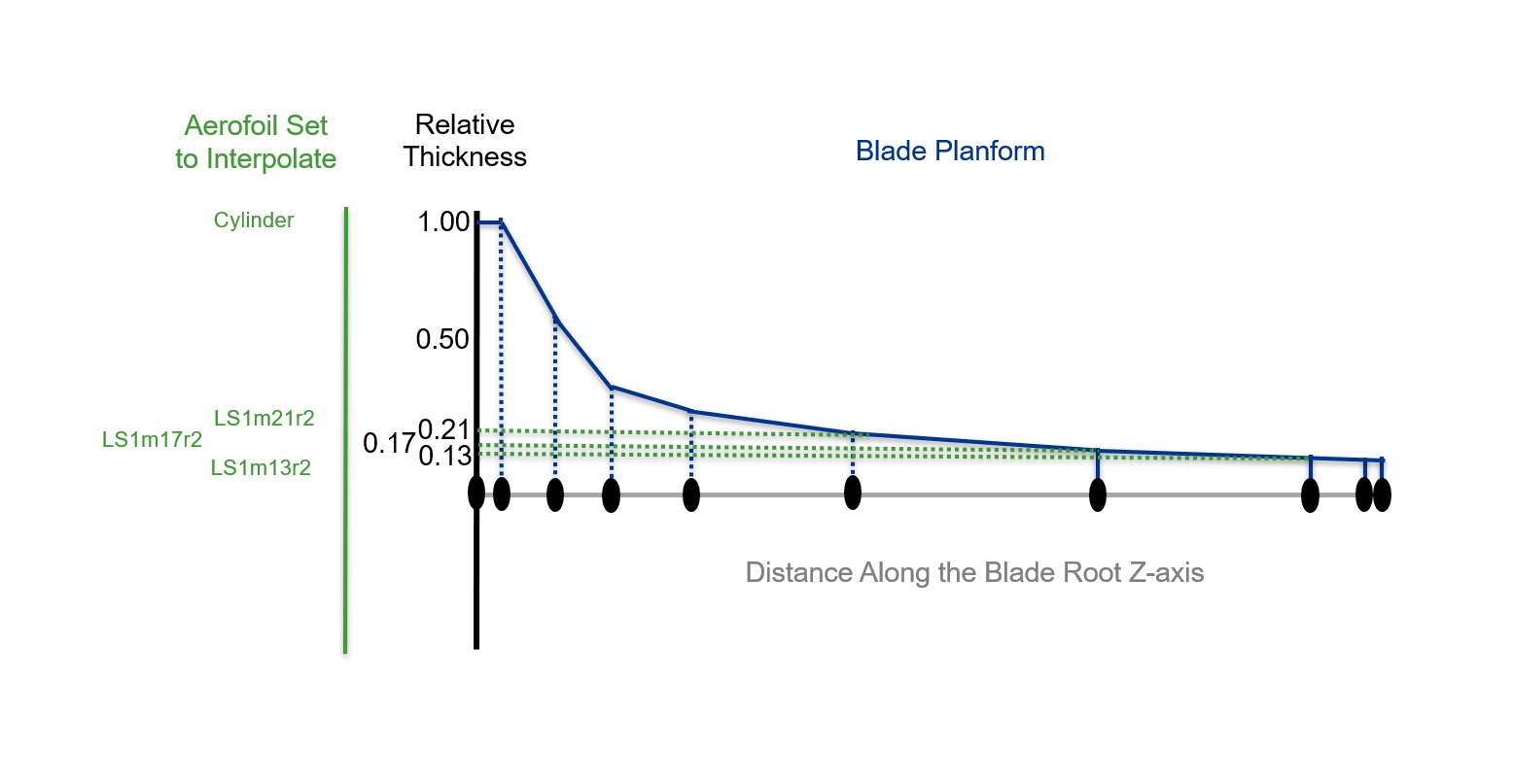
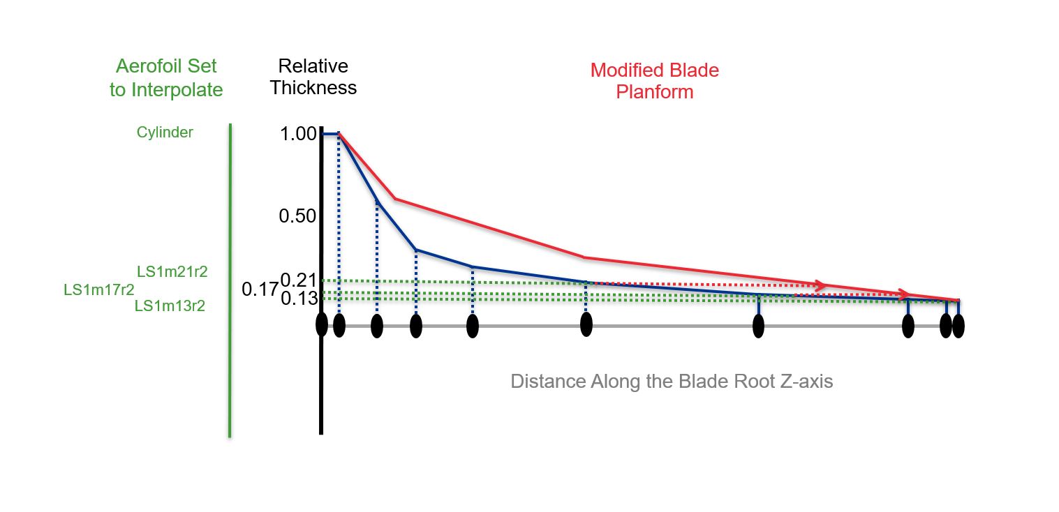
Aerofoil data is specific to a normalized aerofoil shape of a particular relative thickness value. When designing a blade, the thickness distribution of the blade keeps changing, which means the physical aerofoil shape moves to a different location (as seen in Figure 5). To avoid the users having to change the location of the sections and what aerofoils are attached to each section, it is convenient to let Bladed interpolate the aerodynamic data instead. In this example, we will set up the inputs to interpolate over the thickness, but Bladed also supports interpolation (during the simulation) over sets of aerodynamic data of different Reynolds numbers. For more information on this check the Aerofoils article in the modelling section of the documentation.
In Bladed Next Gen., unlike the previous Bladed versions, you are allowed to interpolate any number of aerofoil data, both in thickness and in Reynold's Number.
The JSON input contains a InterpolatedAerofoilLibrary parameter as part of the Blade component definition (explained in aerodynamic properties modelling article). This library contains any number of different sets of aerofoils to be interpolated at a given section.
For a simplified blade simulation, we want all our data from all aerofoils used in our blade to be automatically interpolated. Therefore we want to add all our aerofoils to the InterpolatedAerofoilLibrary as a single aerofoil set.
Note
All the aerofoils used in any set of aerofoils of the InterpolatedAerofoilLibrary must exist in the blade component definition's AerofoilLibrary.
"
{
  ...
  ComponentDefinitions": {
    "Blade": {
      "ComponentType": "Blade",
      ...
      "InterpolatedAerofoilLibrary": {
-       "1_InterpolatedAerofoil_LS1m13r2_LS1m17r2": [
+       "Interpolate_all_aerofoils": [
+         "demo_cyl",
+         "LS1m21r2",
          "LS1m13r2",
          "LS1m17r2"
        ]
      },
      ...
    },
    ...
  }
}
And to assign this aerofoil set to all the sections in our input file. The following snipped shows the assignment of the set of aerofoils to interpolate to the first section, while the planform_demo_a_pcoeffs.json file found in the samples contains the change made in all aerofoil sections.
{
  ...
  "ComponentDefinitions": {
    "Blade": {
      "ComponentType": "Blade",
      ...
      "SectionDefinitions": [
        {
          ...
          "AerodynamicProperties": {
              "Chord": 2.06667,
              "ThicknessToChordRatio": 1.0,
+             "_comment": "A full aerofoil library interpolation is assigned to each aerofoil section so that the aerofoils location is always correct and automatically assigned regardless of geometry changes made by the user",
-             "AerodynamicSection": "demo_cyl"
+             "AerodynamicSection": "Interpolate_all_aerofoils"
          }
        },
        ...
      ],
      ...
    },
  ...
  }
}
Applying the aerodynamic loads to a default reference system: default aerodynamic centre
A last detail needs to be changed to ensure the aerodynamic loads are applied at the pitch axis of the blade when at design wind speed, with no deformations to the planform.
Bladed Next Gen defines the aerodynamic loads at the quarter of the chord location of the aerofoil. However, this is a purely relational data assignation, as there are no physical aerofoil shapes in Bladed. If the aerodynamic data has been calculated at a different location, this is specified in the aerodynamic data itself as the ChordwiseOriginForForcesAndMoments parameter.
If the aerofoil data ChordwiseOriginForForcesAndMoments is different from \(0.25\) then a correction of the aerodynamic moments will be computed and the centre of application of the forces moved to the QuarterChordCoordinateSystem.Origin (see aerodynamic properties modelling article).
However, if the user does not specify a ChordwiseOriginForForcesAndMoments for an aerofoil's aerodynamic data Bladed assumes that the data is positioned at the QuarterChordCoordinateSystem.Origin and no corrections are applied.
Most aerofoil data is calculated at \(ChordwiseOriginForForcesAndMoments=0.25\). This is not, however, the case for the root cylindrical sections. Taken into account that we have already made coincident the QuarterChordCoordinateSystem with ReferenceCoordinateSystem of the section, and this reference system aligned with the root point of origin, by removing the specification of the ChordwiseOriginForForcesAndMoments from any aerofoil that is not computed at the quarter of the chord we are applying all the aerodynamic data in the pitch axis of the blade.
Note
The QuarterChordCoordinateSystem is relevant for knowing where the leading-edge and trailing edge are located, which will impact geometry scaling behaviour structures and noise calculations. Therefore this simplification should not be used in more detailed simulations. In the same way, using this procedure will ensure that the loads are always applied in the same location when scaling the blade shape, but when increasing the detail and fidelity of the simulation the user should care to specify exactly the forces and aerofoils' locations. Alternative reference systems like the leading edge position might be better for scaling - if you need other reference systems for the aerodynamic data, let us know about it.
{
  ...
  "ComponentDefinitions": {
   "Blade": {
        "ComponentType": "Blade",
        ...
        "AerofoilLibrary": {
          "demo_cyl": {
+             "_comment": "the ChordwiseOriginForForcesAndMoments property is removed from the aerofoil data. This means the forces will be directly applied to the origin of the aerodynamic coordinate system",
-             "ChordwiseOriginForForcesAndMoments": 0.5,
              "AerodynamicPerformance": [
                {
                    "Angle": -3.14159265358979,
                    "Cl": 0.0,
                    "Cd": 1.0,
                    "Cm": 0.0
                },
                ...
              ]
          },
          ...
        }
     },
     ...
  }
  ...
}
Removing superfluous components
At this point we have simplified the Blade component as much as we could, heavily relying on the default behaviour of the code to simulate a planform of a blade with only aerodynamic inputs.
When designing a rigid rotor, the turbine itself is fully rigid. Therefore, all other components are unnecessary, since their mechanical properties will not be computed. The use of any components not part of the rotor only add to the complexity of the input file, but they do not change the solution output.
Another reason to discard the extra components is that PerformanceCoefficients is a rotor-only simulation, so the Tower, YawSystem, DrivetrainAndNacelle are all ignored by the solver. You can learn more about this in the performance coefficients documentation article.
The position of the rotor is not important either because PerformanceCoefficients simulates a free-field wind, without wind shear.
To remove a component you only need to remove them from the Turbine.Assembly tree, however it is good practice to remove unused components completely from the input file to declutter and help improve readability and editing:
{
  ...
  "Turbine": {
    "Assembly": {
+     "_comment":"Removed Translation, Tower, YawSystem, Drivetrain and Nacelle, and Generator",
-     "FoundationPosition": {
-       "ComponentReference": "#/ComponentDefinitions/Translation",
-       "Tower_1": {
-         "ComponentReference": "#/ComponentDefinitions/Tower",
-         "YawSystem_1": {
-           "ComponentReference": "#/ComponentDefinitions/YawSystem",
-           "DrivetrainAndNacelle_1": {
-             "ComponentReference": "#/ComponentDefinitions/DrivetrainAndNacelle",
-             "Generator_1": {
-               "ComponentReference": "#/ComponentDefinitions/VariableSpeedGenerator"
-             },
              "Hub_1": {
                "ComponentReference": "#/ComponentDefinitions/IndependentPitchHub",
                "PitchSystem_1": {
                  "ComponentReference": "#/ComponentDefinitions/PitchSystem",
                  "Blade_1": {
-                   "_exercise_1.5": "There is a second blade definition towards the end of the file ('AlternativeBlade'). You can replace the blades in the Assembly with this new definition - but there is currently a limitation on the Performance Coefficients calculation that all the blades must be the same type.",
                    "ComponentReference": "#/ComponentDefinitions/Blade"
                  }
                },
                "PitchSystem_2": {
                  "ComponentReference": "#/ComponentDefinitions/PitchSystem",
                  "Blade_2": {
                    "ComponentReference": "#/ComponentDefinitions/Blade"
                  }
                },
                "PitchSystem_3": {
                  "ComponentReference": "#/ComponentDefinitions/PitchSystem",
                  "Blade_3": {
                    "ComponentReference": "#/ComponentDefinitions/Blade"
                  }
-               },
-               "_PitchSystem_4": {
-                 "_exercise_1.4": "This blade can be re-enabled by removing the underscore.  This will generate a warning so long as the definition of the hub says it should only have 3 blades.",
-                 "ComponentReference": "#/ComponentDefinitions/PitchSystem",
-                 "Blade_4": {
-                   "ComponentReference": "#/ComponentDefinitions/Blade"
-                 }
                }
+               "_comment":"removed unnecessary extra blade"
              }
-            }
-          }
-        }
-      }
    }
  },
  ...
}
Now removing the components is just a matter of cleaning the inputs file:
Removing the generator
{
  ...
  "ComponentDefinitions": {
    ...
+   "_generator_removed": "The generator has been removed",
-    "VariableSpeedGenerator": {
-      "ComponentType": "VariableSpeedGenerator",
-      "GeneratorTimeConstant": 0.0,
-      "PowerFactor": 1.0,
-      "MaximumTorqueDemand": 14400.0,
-      "MinimumTorqueDemand": 0.0,
-      "GeneratorInertia": 60.0,
-      "Losses": {
-        "ElectricalLossesType": "LinearElectricalLosses",
-        "PowerLossAtNoLoad": 0.0,
-        "Efficiency": 95.0
-      }
-    },
    ...
  }
}
Removing the nacelle and drivetrain
{
  ...
  "ComponentDefinitions": {
    ...
+   "_drivetrain_and_nacelle_removed": "removed the nacelle and drivetrain",
-   "DrivetrainAndNacelle": {
-     "ComponentType": "DrivetrainAndNacelle",
-     "PositionOfHubCentre": {
-       "RotorTilt": 0.0698131700797732,
-       "Overhang": 3.7,
-       "HeightOffset": 1.5,
-       "SideOffset": 0.0
-     },
-      ...
-     "Losses": {
-       "ShaftInputTorqueVsResistingTorque": [
-         {
-           "ShaftInputTorque": 0.0,
-           "ResistingTorque": 23000.0
-         },
-         {
-           "ShaftInputTorque": 960000.0,
-           "ResistingTorque": 37000.0
-         },
-         {
-           "ShaftInputTorque": 1280000.0,
-           "ResistingTorque": 49000.0
-         }
-       ]
-     }
-   },
    ...
  }
}
Removing the tower
{
  ...
  "ComponentDefinitions": {
    ...
+   "_tower_removed": "The tower has been removed",
-   "Tower": {
-     "ComponentType": "Tower",
-     "Cans": [
-       {
-         "TowerCanType": "ExplicitTowerCan",
-         "BaseSection": {
-           "MassPerUnitLength": 2935.71,
-           "BendingStiffness": 246000000000.0,
-           "OutsideDiameter": 3.5
-         },
-         "TopSection": {
-           "MassPerUnitLength": 2668.2,
-           "BendingStiffness": 209000000000.0,
-           "OutsideDiameter": 3.36
-         },
-         "CanHeight": 10.0
-       },
-       {
-       ...
-       }
-     ],
-     "AerodynamicProperties": {
-       "CoefficientOfDrag": 0.6,
-       "TowerShadow": {
-         "PotentialFlow": {
-           "CorrectionFactor": 1.0
-         }
-       }
-     },
-     "HydrodynamicProperties": {
-       "CoefficientOfDrag": 1.0,
-       "CoefficientOfMass": 2.0
-     },
-     "PointInertias": [],
-     "Modelling": {
-       "StructuralModellingType": "ModalStructuralModelling",
-       "StructuralModes": [
-         {
-           "DampingRatio": 0.00499999988824129
-         },
-         {
-           "DampingRatio": 0.00499999988824129
-         },
-         {
-           "DampingRatio": 0.00499999988824129
-         },
-         {
-           "DampingRatio": 0.00499999988824129
-         },
-         {
-           "DampingRatio": 0.00499999988824129
-         },
-         {
-           "DampingRatio": 0.00499999988824129
-         }
-       ],
-       "GeometricStiffnessModel": "AxialLoadsOnly"
-     }
-   },
+   "_translation_removed": "The translation moving the tower start assembly point below ground has been removed",
-  "Translation": {
-     "ComponentType": "Translation",
-     "X": 0.0,
-     "Y": 0.0,
-     "Z": -5.0
-    },
    ...
  }
}
Removing the yaw system
{
  ...
  "ComponentDefinitions": {
    ...
+   "_yaw_system_removed": "removed the yaw system"
-   "YawSystem": {
-     "Bearing": {
-       "Damping": 0.0,
-       "Friction": 0.0,
-       "Stiction": 0.0
-     },
-     "Actuation": {
-       "EffectiveGearRatio": 1.0,
-       "LoadBanks": [
-         {
-           "MomentOfInertiaOfMotor": 1.0
-         }
-       ]
-     },
-     "ComponentType": "YawSystem"
-    }
  }
}
Comparison of results
For the results comparison we have available in the samples folder the original demo_a_pcoeffs.json as well as the simplified planform_demo_a_pcoeffs.json and the corresponding aerodynamic information simulations for both the Demo A and the Planform Demo A cases (demo_a_aeroinfo.json and planform_demo_a_aeroinfo.json).
Run both input files in Bladed Next Gen. If you do not yet know how to do this, please refer to the Run a simulation tutorial.
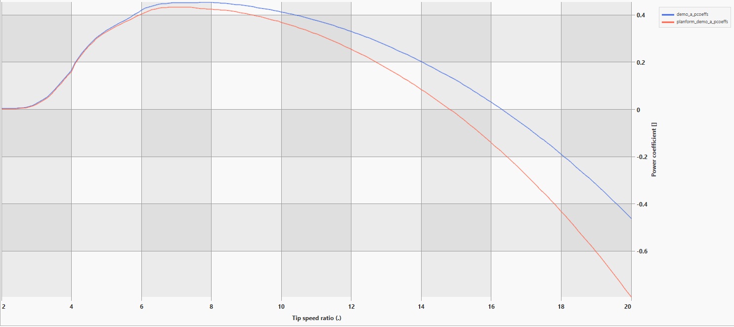
The following plot shows the results you should obtain, and that there is a difference between the original Demo A file and the Planform Demo A results due to differences in the blades definition.
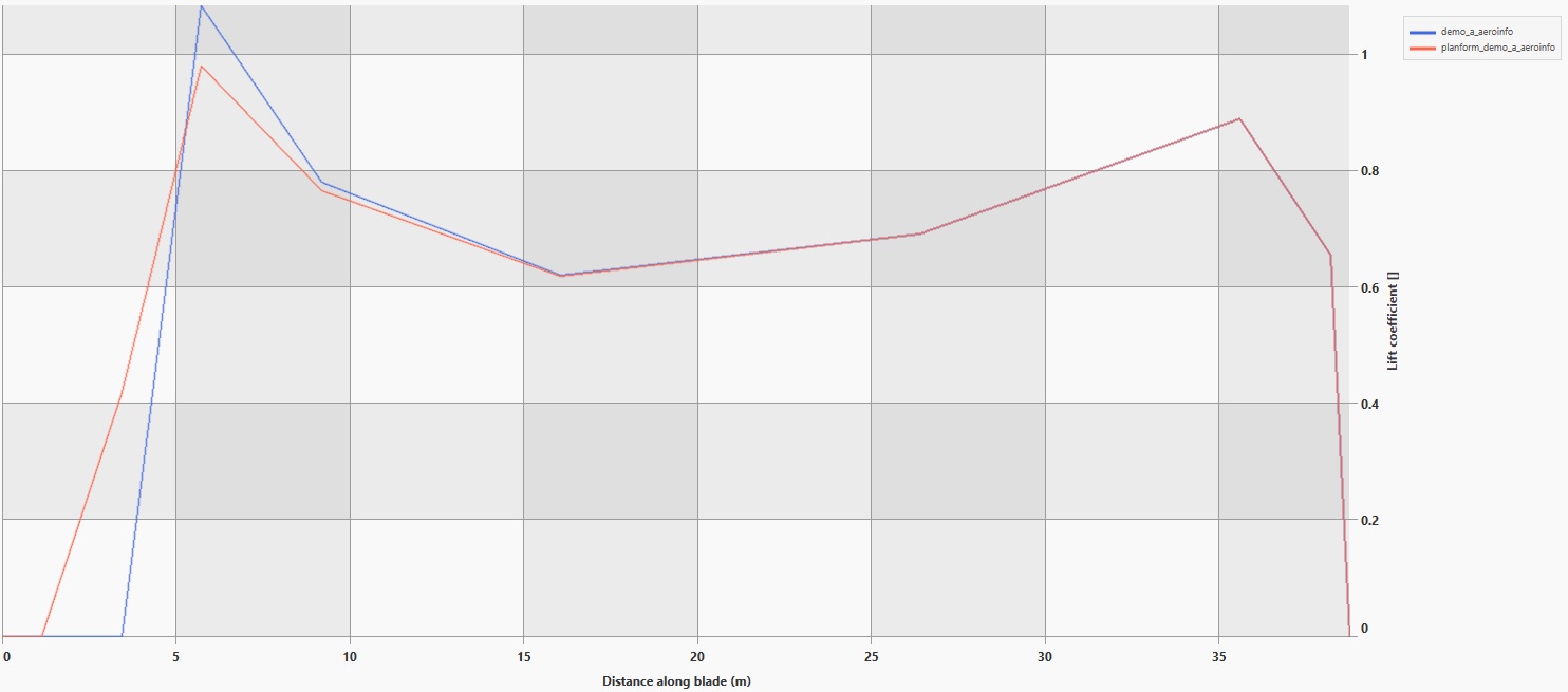
demo_a_pcoeffs.json and planform_demo_a_pcoeffs.json.However, if you run aerodynamic information simulations instead of performance coefficients, you will see that the results difference is due to a more accurate position of the aerofoils on the Planform case. In the Planform case the interpolation ensures that the aerodynamic data is placed and interpolated at the specified thickness. In the original Demo A the 21% relative thickness aerofoil is located at a 22% relative thickness location.
demo_a_aeroinfo.json and planform_demo_a_aeroinfo.json.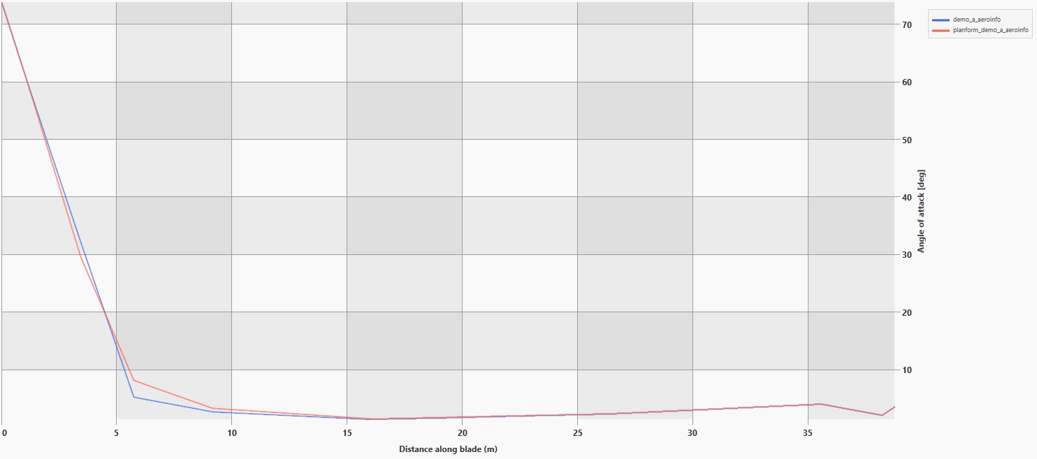
demo_a_aeroinfo.json and planform_demo_a_aeroinfo.json.Both models in this example might not be the best approximation of the Demo A turbine model. This puts the emphasis on the user to use critical thinking to define how many sections and what positions those sections are placed on when modelling a blade.
Try moving the 22% relative thickness section to a 21% thickness position and check how that affects the results in both the demo_a_pcoeffs.json and planform_demo_a_pcoeffs.json.
Conclusions
In this tutorial, we have simplified the inputs file to contain the inputs needed to run a performance coefficient simulation (or aerodynamic information) of a rotor with rigid blades. We have further reduced the size and contents of the file by making use of all the defaulting behaviour of Bladed Next Gen.
We have observed that the results of the performance coefficient simulation are not the same for the demo_a_pcoeffs.json and the planform_demo_a_pcoeffs.json inputs due to a change in the interpolation of the aerofoils. The interpolation of the aerofoils assures that regardless of the blade design, the aerofoil data is placed at the correct thicknesses and interpolated to any other thicknesses.
Further steps after this procedure could be to include the file and simulation into a geometry optimisation loop, or wrap it with a graphical interface to allow for the fast manual iteration of the blade planform. This can be done without changing aerofoils or caring for their absolute location in the blade, taking advantage of the unlimited aerofoil interpolation feature present in Bladed Next Gen.
