Define a blade in JSON
Summary
This tutorial introduces you to the basic blade component in Bladed. You will have the opportunity to experience how you can define multi-blade rotors and blades with different definitions.
Prerequisites
- Latest version of Bladed Next Gen and Samples installed including the Bladed Python packages.
- Licence for Bladed Next Gen (request a licence).
- A text editor with JSON support.
We would recommend opening the samples folder in VS Code to follow along with these tutorials.
If you do not yet know how to run a simulation, please follow the instructions and checks in the Get started and Run a simulation tutorials before continuing.
Subjects Covered
By the end of this tutorial you should have:
- Understood how to add and remove blades from the turbine assembly.
- Switch between blade definitions in your input file.
- Modify the blade component.
demo_a_pcoeffs.json
In tutorial we will use the performance coefficients calculation based on the demo_a model (demo_a_pcoeffs.json). This is a very simple model which has been annotated with _description, _comment, and _exercise tags. These tags can help you understand the structure of the model better.
Note
Currently all values in the input decks are in S.I. units, which for many users this will be the preferred behaviour. It is the intention to implement a system of units in JSON for users who interact with the file a lot, as they may prefer to use rpm for rotor speed, degrees for wind direction, etc.
Are alternative units important to you? Let us know about it
Exercise 1.4: Adding a fourth blade
This exercise makes a basic change to the turbine structure - it adds an additional blade to the model, making it a four-blade turbine. For an introduction to how the turbine configuration is specified in the Bladed Next Gen input deck refer to the Assemble a turbine tutorial. The JSON is already in place; you just need to remove the underscore from in front of _PitchSystem_4:
...
- "_PitchSystem_4": {
+ "PitchSystem_4": {
    "ComponentReference": "#/ComponentDefinitions/PitchSystem",
    "Blade_4": {
      "ComponentReference": "#/ComponentDefinitions/Blade"
    }
  }
...
Run a simulation with your modified input file.
The output file will generate the following error:
*** ERROR:   The following errors were found whilst building the turbine:
More child components have been specified than Hub_1 has connectable nodes.  Please check your Assembly definition.
A valid connection for PitchSystem_1 could not be found on component Hub_1   Exiting with return code 2
Just adding an extra blade to the turbine assembly is not enough, the hub needs to explicitly define the number of blades it can carry.
This is done by locating the IndependentPitchHub component where the blades are attached in the assembly tree.
In the IndependentPitchHub component definition change the number of blades from 3 to 4.
...
"IndependentPitchHub": {
  "ComponentType": "IndependentPitchHub",
- "NumberOfBlades": 3,
+ "NumberOfBlades": 4,
  ...
}
Now you can run the simulation without any problems.
You will be able to see in the command line output that the simulation is running with 4 blades in the following message:
*** Note: Analysing turbine demo_a_pcoeffs: clockwise rotation, upwind, 4 blades
All these messages will also appear in the $ME output file.
Exercise 1.5: Interchanging the blade component
This exercise replaces the demo_a blade with a stripped-down blade. This blade is not meant to be in any way a realistic blade model - it has just been provided for the purposes of this tutorial.
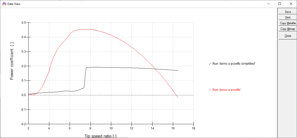
If you look under the ComponentDefinitions node, you will find the original blade definition (just called Blade). If you look below it, you should find a second blade component named AlternativeBlade. The exercise is to modify the Assembly reference of each blade so that it references AlternativeBlade. The AlternativeBlade is the last component and can be found right at the bottom of the JSON input file.
"Blade_1": {
  "ComponentReference": "#/ComponentDefinitions/AlternativeBlade"
}
Run a simulation with your modified input file.
If you now open the results in Bladed Results Viewer, you should be able to notice the deterioration in the blades' performance:

Tip
At this stage, steady calculations cannot be run with different blade models, as the algorithm for averaging the results has not been agreed upon. However, time-domain simulations have been run with different blade models - although the results have not been verified.
Exercise 1.6: Modifying the blade definition
The last exercise in this file is less structured. If you have a look around the definition of the blades, you will see that there are a number of numerical values to modify. Spend some time modifying the blade and getting more familiar with the definition of blade geometry. Run bladed.exe with your modified input file, and view any of the outputs you think should have changed.
Conclusions
By this point it is hoped that you will have a general understanding of:
- How to add and remove blades from the turbine assembly.
- Switching between blade definitions in your input file.
- Modifying the blade component.