Assemble a turbine in JSON
Summary
Learn how to build a turbine in the new Bladed Next Gen JSON input data model using it's assembly feature.
Prerequisites
- Latest version of Bladed Next Gen and Samples installed including the Bladed Python packages.
- Licence for Bladed Next Gen (request a licence).
- A text editor with JSON support.
Subjects Covered
By the end of this tutorial you should have:
- Understand what is the turbine assembly tree property.
- Produce a turbine assembly template.
- Add components to a turbine assembly.
- Model a rotor.
- Model a generic turbine.
Assemble_a_turbine.json
We would recommend opening the samples folder in VS Code to follow along with these tutorials. In this section of the tutorial we will use an incomplete IEA 15MW NREL steady operational loads JSON input file assemble_15MW_SteadyOP.json.
If you do not yet know how to run a simulation, please follow the instructions and checks in the Get started and Run a simulation tutorials before continuing.
The assembly structure
Open the assemble_15MW_SteadyOP.json input file and observe in line 50 that the Assembly property of the Turbine is missing. If you hoover your mouse over the Turbine you will see the following error message:

Assembly property.Under the commented line 50 "_ADD_ASSEMBLY": "Add an assembly object in this location to build your turbine model using the pre-defined components in the ComponentDefinitions object" type "Assembly": and notice how it offers you to autocomplete the assembly with a pre-prepared template:

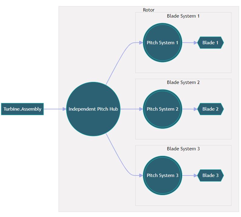
Assembly property rotor template auto-complete.If you accept this template auto-complete it will automatically write the following data:
{
  ...
  "Turbine":{
    ...
+   "Assembly":{
+     "_Template": "Rotor hub and blades",
+     "Hub": {
+       "_comment": "This is the single root node, for a hub component, under which 3 'child' nodes have been defined, modelling the pitch system and blades.",
+       "ComponentReference": "#/ComponentDefinitions/<component-name>",
+       "PitchSystem1": {
+         "_comment": "Each child node itself, references it's component, and can have an unbounded number of 'child' nodes.",
+         "ComponentReference": "#/ComponentDefinitions/<component-name>",
+         "Blade": {
+           "ComponentReference": "#/ComponentDefinitions/<component-name>"
+         }
+       },
+       "PitchSystem2": {
+         "ComponentReference": "#/ComponentDefinitions/<component-name>",
+         "Blade": {
+           "ComponentReference": "#/ComponentDefinitions/<component-name>"
+         }
+       },
+       "PitchSystem3": {
+         "ComponentReference": "#/ComponentDefinitions/<component-name>",
+         "Blade": {
+           "ComponentReference": "#/ComponentDefinitions/<component-name>"
+         }
+       }
+     }
+   }
  }
}
This is the basic structure of a rotor only model, typically used in Aero Information and Performance Coefficient simulations.
The names of each component in the assembly tree are user-defined and do not hold any significance to the data model itself. As long as the connection nodes of different components are compatible with each other, the user can build a structure however they like. The name Blade could be renamed something else and the assembly would still have the same structure.
Model the IEA 15MW rotor
Now that you have a template set on your input file it is time to build a rotor using the existing component in your input file.
Locate the ComponentDefinitions property in your input file. Your editor might allow you to collapse the nodes on the input file so that you see only a list of the components available.
You should be able to see the following components:
{
...
  "ComponentDefinitions": {
    "IEA15Blade": {
      "ComponentType": "Blade",
      ...
    },
    "IEA15DrivetrainAndNacelle": {
      "ComponentType": "DrivetrainAndNacelle",
      ...
    },
    "IEA15Hub": {
      "ComponentType": "IndependentPitchHub",
      ...
    },
    "IEA15PitchSystem": {
      "ComponentType": "PitchSystem",
      "NumberOfBlades": 3,
      ...
    },
    "IEA15Tower": {
      "ComponentType": "Tower",
      ...
    },
    "IEA15Generator": {
      "ComponentType": "VariableSpeedGenerator",
      ...
    }
  }
}
Observe that the name of the component does not define what type the component is, or what properties it holds inside. The name of the component is arbitrary and user-defined, it is the ComponentType property that assure we are using a Blade, or a Tower, or any other component. So always check the component type before using a component to build your assembly.
To build a rotor all we need are an IndependentPitchHub, a PitchSystem and a Blade.
On the predefined template replace the <component-name> in each of the component references with the corresponding names of the components as they are named in the ComponentDefinitions:
{
  ...
  "Turbine":{
    ...
    "Assembly":{
      "_Template": "Rotor hub and blades",
      "Hub": {
        "_comment": "This is the single root node, for a hub component, under which 3 'child' nodes have been defined, modelling the pitch system and blades.",
-       "ComponentReference": "#/ComponentDefinitions/<component-name>",
+       "ComponentReference": "#/ComponentDefinitions/IEA15Hub",
        "PitchSystem1": {
          "_comment": "Each child node itself, references it's component, and can have an unbounded number of 'child' nodes.",
-         "ComponentReference": "#/ComponentDefinitions/<component-name>",
+         "ComponentReference": "#/ComponentDefinitions/IEA15PitchSystem",
          "Blade": {
-           "ComponentReference": "#/ComponentDefinitions/<component-name>"
+           "ComponentReference": "#/ComponentDefinitions/IEA15Blade"
          }
        },
        "PitchSystem2": {
-         "ComponentReference": "#/ComponentDefinitions/<component-name>",
+         "ComponentReference": "#/ComponentDefinitions/IEA15PitchSystem",
          "Blade": {
-           "ComponentReference": "#/ComponentDefinitions/<component-name>"
+           "ComponentReference": "#/ComponentDefinitions/IEA15Blade"
          }
        },
        "PitchSystem3": {
-         "ComponentReference": "#/ComponentDefinitions/<component-name>",
+         "ComponentReference": "#/ComponentDefinitions/IEA15PitchSystem",
          "Blade": {
-           "ComponentReference": "#/ComponentDefinitions/<component-name>"
+           "ComponentReference": "#/ComponentDefinitions/IEA15Blade"
          }
        }
      }
    }
  }
}
You will notice that you need to assign several times the same PitchSystem and the same Blade to the 3 IndependentPitchHub blade nodes. To check how to increase this number to 4 blades and to model different blades in the same rotor check the Modelling blades in JSON tutorial.
You now have a rotor that you should be able to run in Aero Information and Performance Coefficient simulations. Check the Setting up a Bladed simulation in JSON tutorial if you want to try running the rotor Performance Coefficients with the present assembly.
Model the IEA 15MW turbine
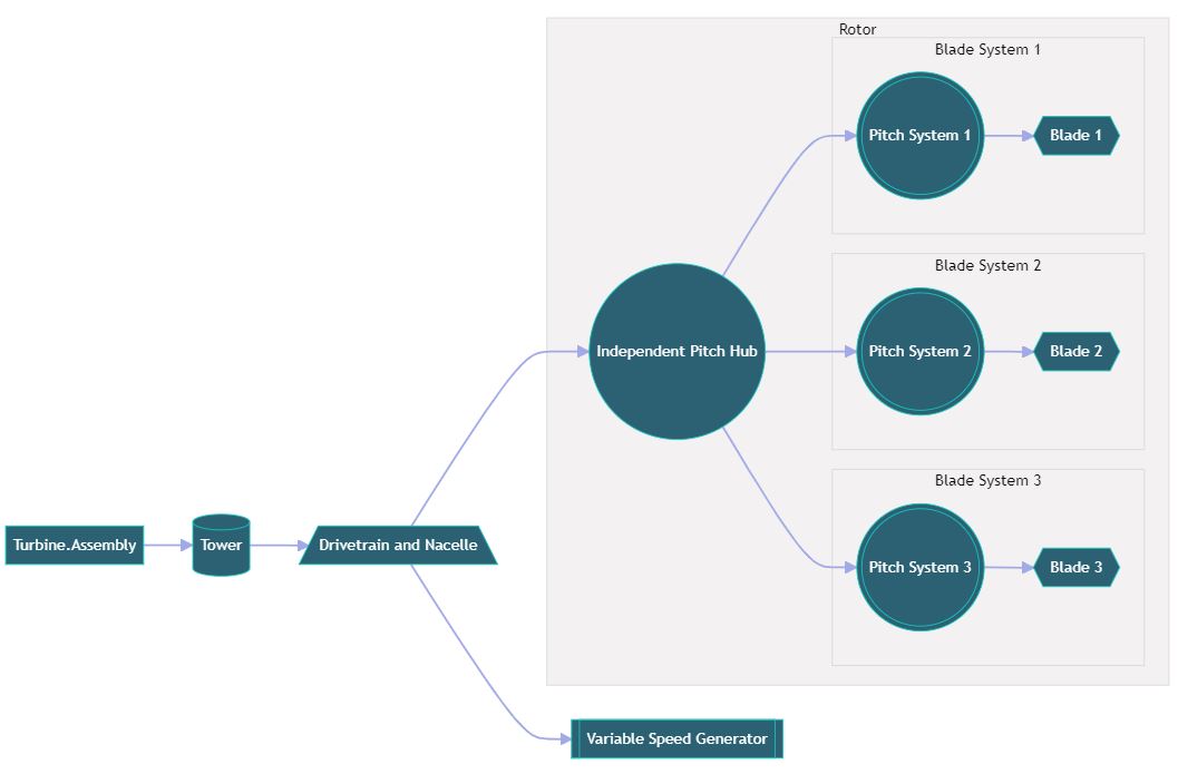
To model a basic turbine we will have to complete the assembly tree and add some extra components to it, namely a DrivetrainAndNacelle, a Tower and a VariableSpeedGenerator to the assembly tree. We will again reuse the components that are already available in the input file.
We will nest the already existing IEA15Hub assembly on the IEA15DrivetrainAndNacelle, and in turn the IEA15DrivetrainAndNacelle will be nested on the IEA15Tower.
The IEA15DrivetrainAndNacelle allows for two types of assembly nodes:
- an
IndependentPitchHubto be attached to the low speed shaft - a
VariableSpeedGeneratorto be attached the high speed shaft
    "Assembly": {
+     "Tower": {
+       "ComponentReference": "#/ComponentDefinitions/IEA15Tower",
+       "DrivetrainAndNacelle": {
+         "ComponentReference": "#/ComponentDefinitions/IEA15DrivetrainAndNacelle",
+         "Generator": {
+           "ComponentReference": "#/ComponentDefinitions/IEA15Generator"
+         },
          "Hub": {
            "ComponentReference": "#/ComponentDefinitions/IEA15Hub",
            "PitchSystem1": {
              "ComponentReference": "#/ComponentDefinitions/IEA15PitchSystem",
              "Blade1": {
                "ComponentReference": "#/ComponentDefinitions/IEA15Blade"
              }
            },
            "PitchSystem2": {
              "ComponentReference": "#/ComponentDefinitions/IEA15PitchSystem",
              "Blade2": {
                "ComponentReference": "#/ComponentDefinitions/IEA15Blade"
              }
            },
            "PitchSystem3": {
              "ComponentReference": "#/ComponentDefinitions/IEA15PitchSystem",
              "Blade3": {
                "ComponentReference": "#/ComponentDefinitions/IEA15Blade"
              }
            }
          }
        }
+     }
    }
You have now conclude the modelling of the IEA 15MW turbine. The file that you have produced should be identical to the NG_IEA_15_Onshore_SteadyOP.json file in the samples deck, but you might need to revert it back to a Steady Operational Loads simulation if you have attempted to run the rotor only case. Check the Setting up a Bladed simulation in JSON tutorial if need help running a Steady Operational Loads simulation.
Allow assembly connections between components
The assembly tree is very versatile but it still has constrains. Not all components can be attached together. For a comprehensive list of what components can be connected to each other please refer to the assembly allowed node connections modelling documentation article.
Try out different configurations and component names
You have now completed the tutorial and should be able to build a generic turbine of your own.
You might also want to try out some of the following:
Experiment changing names of components in the
ComponentDefinitionsand interchanging different user defined components in theAssemblytree.Bladed Next Gen aims to be a much more versatile tool than the previous Bladed version, allowing for custom made turbine assembly structures. This is a work in progress, but you can check in the modelling documentation what are the allowed node connections between the supported components and build your own unique turbine.
Another option is to try and model imbalances and yaw flow misalignment by defining blades with different properties for the same rotor (as seen in the Modelling blades in JSON tutorial), or using the generic translation and rotation components (as seen in the Model component displacements tutorial).
Conclusion
Concluding this tutorial you will now have enough knowledge to model a wind turbine in Bladed Next Gen. You will have understood what is the Assembly and how to build the assembly tree to model a turbine of your own. You will have understood how to place and interchange components and build bespoke turbine models.

