About the Drivetrain and Nacelle
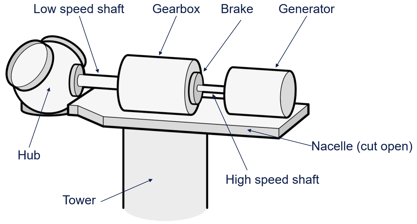
This section provides an overview of the DrivetrainAndNacelle component which includes the nacelle cover that houses the gearbox, drive shafts, brakes and the positioning of the hub centre. The generator is defined as a separate component.

The body-fixed frame of the DrivetrainAndNacelle component is often attached to the distal node of the Tower or YawSystem.
The following shows an overview of the articles that describe the properties defined within the DrivetrainAndNacelle component:
- Position of the Hub Centre: Describes the hub centre’s location relative to the body-fixed frame of the
DrivetrainAndNacelle. - Gearbox Properties: Consists of the gearbox ratio and gearbox inertia properties.
- Drivetrain Shafts: Includes low-speed and high-speed shafts that can be made flexible.
- Mechanical Losses Model: User-defined representation (e.g., lookup table or linear ramp) for gearbox efficiency and other losses.
- Shaft Brakes: A series of brakes can be defined for turbine parked and stopping simulations.
- Slipping Clutch: Consists of a clutch between the gearbox and the generator.
- Mounting Flexibility: Pallet mounting flexibility of the transmission system.
- Mass and Static Inertia: Definitions of the static components of the drivetrain and nacelle
- Rotational Inertia of the Drivetrain: Overview of how the rotational inertias are defined.
- Nacelle Cover: Describes the geometric and aerodynamic characteristics of the cover.
- Outputs: Results related to drivetrain and nacelle components.
A multibody diagram is presented here illustrating the available options and how they connect.